Validation of computerised systems
|
Here you will find answers to the following questions:
|
This chapter covers normal validation cases. Retrospective validation, which may be necessary if the regulatory requirements are changing or if the functionality of the system is extended to cover GxP relevant functionality. Retrospective Validation is covered in chapter 9.E.8 Dealing with existing systems (legacy systems). The procedure how to validate should be regulated in standard operating procedures (SOP). These describe the appearance and contents of the validation documents and guarantee that validations have a uniform appearance and all systems are handled consistently.
9.E.1 Responsibility and organisation
9.E.1.1 Responsibilities
Clear responsibilities are a cornerstone for a successful project. In a validation project, the responsibilities can be assigned as follows (figure 9.E-1).
|
Role |
Responsibility |
|---|---|
|
Project manager |
|
|
System operator |
|
|
Quality assurance |
|
|
Validation team |
|
|
Supplier (software and hardware) |
|
Note that the validation team may include varying numbers of people, depending on the scope of the project. For a simple spreadsheet, the team sometimes only consists of one person, while for larger projects, it may be practical to involve the whole user organisation.
9.E.1.2 Organisation
Depending on the organisational format of a company, responsibilities may be distributed in different ways. A company can decide between computer validation with or without external service providers.
In order to achieve validation of computerised systems quickly, the involvement of external service providers means that this task can be assigned to a specific group. With sufficient resources, a validation team of this type can validate all systems in a department within a very short timescale. This process can be further accelerated with external support from service provider companies, consulting companies and additional resources for time-consuming testing procedures. This is often suitable if an inspection is looming and significant deficiencies are known, if a unit is undergoing reorganisation, or to bring a newly acquired site up to a certain standard. The major disadvantage of this method is that the validation process is not sustainable. In addition, there is a risk that despite the existence of validation documents, an inspection discovers deficiencies since the local personnel is unable to sufficiently "sell" the work performed. For an experienced inspector, this type of "last-minute" validation is easy to identify, since all the validation documents are compiled within a relatively short period. It is also more difficult to maintain the validated status, since there is a lack of fundamental understanding within departments.
|
With external participation |
With internal employees only |
|
|---|---|---|
|
Speed of validation |
Fast |
Slow |
|
Depth of validation |
Detailed |
Superficial |
|
Inspection characteristics |
All documents have been compiled within a short timeframe |
Documents tend to be non-uniform and are in different styles |
|
User involvement |
Little evidence |
Very obviously available |
|
Knowledge gained by the company |
Little |
A lot |
|
Workload for staff |
Low |
High |
The opposite organisation is a procedure involving exclusively internal staff. In this case, each production department and each laboratory is responsible for its own validation. The advantages, such as increased knowledge gained by the company, good integration of the workforce and easier maintenance of the validated status, are measured against the absence of depth, non-uniform appearance - if no clear specifications are provided -, the time required and the increased workload for employees. Figure 9.E-2 shows a comparison of both variants.
In practice, a middle ground is recommended, which combines the best aspects of each extreme position.
9.E.1.3 Validation policy
Validation policy is used here to describe a superordinate, internal company definition that describes the systematic procedure. The policy must be supported by the highest management level of the company to ensure that validation is executed successfully.
The following points should be set in the policy:
- Purpose: why should computerised systems be validated?
- Area of application: which systems require validation?
- Responsibilities: user involvement, integration of quality assurance and its independence
- Basic procedure: planning, execution, reports, monitoring of changes, periodic review
- Validation strategy: integration into the development and procurement cycle of computerised systems
- List of points that must be dealt with during validation (see chapter 9.E.2 Validation plan)
9.E.1.4 Inventory of systems
The inventory is the pivotal point for the successful realisation of validation goals. Without an inventory, not only is the status of individual systems unclear, but it is also difficult to determine which resources should be invested in which systems.
The most difficult issue in terms of the inventory is the definition of a computerised system. If a system is defined at too low a level, this can have just as negative an effect as if a system is defined too generally.
Example: A building control system can be entered in the inventory as a central system with dozens of subsystems, or just as a single system for building monitoring. Laboratory equipment with twelve networked chromatography stations can appear in the inventory as thirteen systems or only as one. The more finely an inventory is structured, the more simple it becomes to maintain the validated status. If a module is exchanged in the building control system, this module and its interfaces to the main system then need to be revalidated. If the building control system appears as the only system in the inventory, in time, revalidation can lead to an unclear situation that is difficult to maintain, and which is also difficult to explain during inspections. On the other hand, an inventory that is too detailed can easily lead to a large amount of unnecessary work.
This inventory is also known as a CSV ((Computer System Validation) inventory).
9.E.2 Validation plan
The validation plan should contain the following elements:
- System description
- Responsibilities
- Process of the validation
- Acceptance criteria
- Validation registry - planned deliverables
9.E.2.1 System description
A brief narrative system description is normally sufficient. The surrounding systems and interfaces should also be briefly listed. This way, the scope of the validation can be delimited.
For a spreadsheet for content uniformity determination, a system description can be formulated in a few sentences as follows (figure 9.E-3).
|
System description |
|---|
|
9.E.2.2 The validation process
It has proven useful to determine which validation deliverables should be created in which phase. It is often not clear from the beginning in which qualification phases (IQ, OQ, PQ) certain tests and validation activities should be performed.
For example, it can be useful to perform a stress test in early phases of development if the process is a hardware-related machine-oriented system such as an autoclave control. Here it is particularly important to check that the sampling frequencies of the sensors do not cause a functional impairment due to system load.
In a pure data processing system such as an LIMS (Laboratory Information Management System) or a documentation management system, it is more practical to execute the stress test in a later phase, to ensure that the system performance is sufficient to keep pace with the quantity of user inputs.
The validation strategy depends on the classification of the software. Validation plans can also be used to estimate the required resources (see figure 9.E-4).
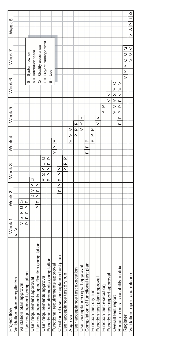 |
It is important that the plans and specifications are completed and approved before execution of the corresponding activities.
9.E.2.3 Acceptance criteria
The acceptance criteria must be determined in advance at the individual stages of the test. The more simply and the clearer the user requirements, function specifications or system specifications (see chapter 9.C.1 "V-Model") are compiled, the easier it is to derive the appropriate tests from them.
9.E.2.4 Planned deliverables
A list of deliverables to be compiled during the validation, known as a validation registry, has many advantages:
- The procedure can be rapidly adjusted to suit the system category and the risk, so that no work time has to be invested in unnecessary deliverables, according to the motto "as little as possible - as much as necessary".
- The project management can quickly get an overview of the current status in the project.
- Quality assurance can simply check that all deliverables have been documented properly before the system is released.
- In the event of an inspection, specific documents can be safely and quickly localised, even several years later.
The following table (figure 9.E-5) can also easily be implemented in practice, for example, by adding a "target data" column in the project control, in order to determine target data for the individual deliverables; by adding a "responsible" column or by adding a control box, in order to tick off the deliverables during an internal release inspection. The individual deliverables are described in the following sections.
|
Phase |
Deliverable |
|---|---|
|
Inventory |
Classification |
|
Risk evaluation |
|
|
Inventory |
|
|
Validation |
Validation plan |
|
Validation report |
|
|
Validation registry |
|
|
Qualification plan |
|
|
Qualification report |
|
|
Supplier management |
Supplier assessment |
|
Specify & Design |
User requirements |
|
System specifications |
|
|
Development standards |
|
|
Project change control SOP |
|
|
Functional risk assessment |
|
|
Technical design |
|
|
Build |
Source code, configuration, adjustment |
|
Technical documents (for IT) |
|
|
Test |
Test protocols |
|
Unit/integration test specifications |
|
|
Unit/integration test report |
|
|
Installation test documentation |
|
|
System test documentation |
|
|
Acceptance test documentation |
|
|
Traceability matrix |
|
|
System configuration basis |
|
|
Implement & Use |
Implementation plan |
|
User SOPs |
|
|
Change control SOP |
|
|
Security administration SOP |
|
|
SOP for backup and restore |
|
|
SOP for archiving |
|
|
SOP for user training |
|
|
Service level agreement |
|
|
SOP for periodic review |
|
|
Plan for system shutdown |
|
|
System retirement report |
9.E.3 Specifications (user requirements/technical
specification) for hardware and software
The different specifications differ in the level of detail and the target group intended to work with each specification. Since a standard and commonly understood language is important for a successful project, it is useful to define the technical expressions.
To ensure that the requirements have been fully implemented and later, to check that they have been fully tested, a Traceability matrix is compiled. This is a simple tabular comparison of the different requirements.
Terms
User requirement specification: In the user requirements, the requirements defined by users are summarised in a specification for the computer system (user requirement specification, URS).
Technical specification: The user requirements from the URS are then described by the supplier in more detail and using technical language in the technical specification.
Traceability matrix: A tabular overview for traceability of the requirements across the various specification stages and to ensure that the corresponding specifications can be tested.
The user requirement specifications are the specifications for the computer system (URS). These user requirements are then described by the supplier in more detail and in technical language in the technical specification. In practice, good specifications usually provide a good guarantee that the system will subsequently achieve high user acceptance and will function as required. The most important quality attributes of good specifications are comprehensibility, clarity, brevity, and a structured layout of the requirements. Extensive literature is also available on user requirements. The book Software Requirements by Karl E. Wiegers includes some example of good and poor user requirements.
Example
|
Poor |
The system must be able to administrate user authorisations and projects with different access authorisations. |
|
Good |
The system must be able to administrate up to 35 users with the authorisation levels read, write, and delete in a project-specific manner for more than 5000 projects in a way that ensures that entries can only be made at one point and can be inherited for the other projects, unless the person or the project is included in an exception list. |
|
Too detailed and yet still too imprecise |
The system must be able to administrate all users in the analytical development department. However, Mr. Distiller must not be permitted to overwrite the methods entered by Mr. Burner. Jonny Trainee has to change to a new department every three months. This change must be possible using Drag and Drop. Dr. Eusebius Smoke, our superior, must be able to view all methods. |
The table (figure 9.E-7) shows some general problems that can occur with inadequate user requirements and attempts to present possible corrective measures.
|
Symptom |
Causes that need to be resolved |
|---|---|
|
Incomplete user requirements with insufficient level of detail |
|
|
Poorly described scope |
|
|
Decisions that have already been made are repeatedly questioned and overruled |
|
|
Discussions on word choice |
|
|
Users don't know exactly what they want. |
|
|
Solutions are listed as requirements. |
|
For the management of user requirements of more complex systems, commercial management programs are available that can not only administrate requirements, but also compile the requirements traceability matrix at the same time. For simple systems, a spreadsheet is usually sufficient.
9.E.4 Unit, integration and acceptance tests
It is mathematically impossible to prove by testing that even an only moderately complex computerised system does not have any errors. This is clearly proven by Boris Beizer in the book Software Testing Techniques . Therefore, in particular for testing, it is necessary to implement the available resources in order to demonstrate that the system functions as it should.
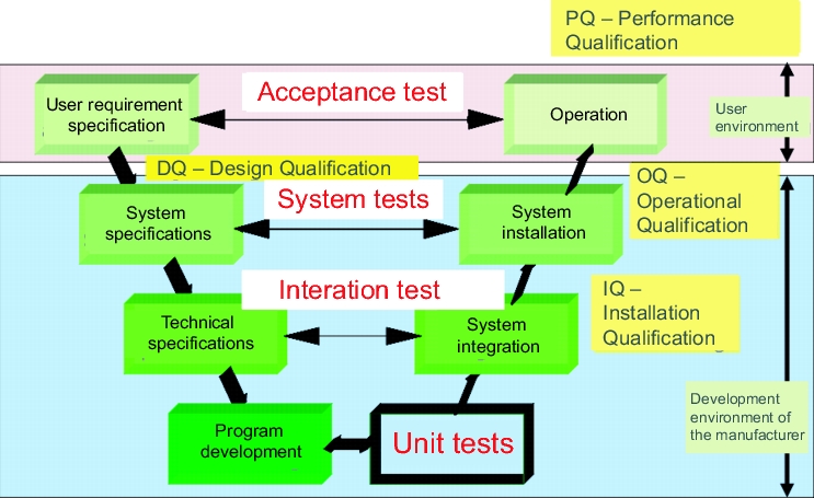
Testing is performed on different levels (see figure 9.E-9), at which the system is always tested against the relevant specification.
- User acceptance tests: Testing against user requirements
- System tests: Testing against system specifications
- Integration tests: Testing against the technical specification, functional specifications, or system specifications
- Unit tests: Testing of individual programming steps. These individual sections are sometimes also referred to as modules or units.
White box testing and black box testing are test strategies. In white box testing, the internal process flow of the program is known and the individual decisions and subprograms can be tested. In black box testing, only inputs and outputs are visible. The process is known, but not how it functions and is implemented in detail. As an analogy, we can view "black box testing" as an inspection of the car with the bonnet closed, while in white box testing, the bonnet is opened in order to follow exactly what happens, for example, when the gas pedal is pressed.
The following table shows the individual test procedures from a practical perspective, and where they are best implemented (figure 9.E-8).
|
Risk |
|||
|---|---|---|---|
|
Test level |
Low |
Medium |
High |
|
Unit test |
Positive function test |
Variable definition Buffer |
Source code review |
|
Integration test |
Interfaces Buffer |
Branch testing |
|
|
System test |
Stress test |
Capacity test |
|
|
Acceptance test |
Negative test |
||
9.E.4.1 Test stages in the V model
The test stage describes the section of the software life cycle on which a test is performed. A differentiation is made between the unit test, the integration test and the acceptance test (figure 9.E-9).
 |
Unit test
In this test, the individual steps of the programming, also known as modules, are tested. In a customer built add-on, for example a macro that reads the values directly from the interface of a laboratory balance, only this add-on is subject to the unit test. For firmware, standard software and configurable software, these activities are carried out by the supplier and should therefore be checked during the supplier audit. Unit tests are generally performed by the software developer themselves, although this is viewed as unacceptable in integration tests and system tests for high-risk systems. In this case, the developer and the tester should not be the same person.
Integration test
In this test, the interaction between the modules is tested. This is usually tested in a test system and not in the productive system. The test is performed against the functional specifications.
To name a simple example, if a programmer compiles a macro for an interface from a laboratory balance to Excel, in the integration test, he will check whether their macro runs satisfactorily in the customer's Excel environment (which is either loaned to the programmer by the customer, or which the programmer replicates in their own system) and ensures that it does not have any negative effects on Excel or on the balance. This test is performed against a test plan a written test specifications that are defined in advance. In this case, the test specifications would test the interface commands of the balance and the correct transfer of balance commands such as adjust tare, set to zero, read weight values. When reading weight values, these would be checked against the calibration values and the speed with which the weights are read would also be tested.
Roughly speaking, the integration test represents the installation qualification and should therefore meet the manufacturer's specifications.
It is also important, however, to maintain a pragmatic approach. Although a test should logically and conceptually be executed in this phase, sometimes this cannot easily be achieved, and the test is performed practically as a by-product in the system test or in the operational qualification.
System test
When the system is tested against the system specification, this is known as the system test. This is normally performed by the supplier.
In general, the system test corresponds to the operational qualification. The system is tested against the operational specifications (chapter 6.F Operational qualification(OQ)).
Using the example of the macro for controlling a laboratory balance, the system test can mean that the macro is installed on the corresponding machines in the lab (as an exception, and to use a pragmatic method to ensure that the target environment is 100% correct), and this installation is then tested. As a potential risk of this type of installation process, existing files on the computer may be overwritten, which could impair the function of the device. Therefore, these tests should not only incorporate the technical system specifications, but also a test of the environment. Questions that should usually be asked include:
- Does the system react quickly enough?
- Are sufficient reserves available for processing the input?(What happens when the weight entries are made in rapid succession, e.g. if the button for entering weights is pressed twice?)
- Are temporary files created on the hard drive that would gradually fill the hard disk?
This example is used to clearly demonstrate that the limits must not always be dogmatically complied with, but rather a pragmatic approach with more simple methods leads to results that more closely reflect reality. After all, what is the use of the test procedure if at the end of the day, an unforeseeable network bottleneck threatens the usability of the system, or if other unpredictable factors later become an obstacle.
Acceptance test
The test against user requirements is the last test stage before a system can be released for production following successful completion and finishing of the validation report.
9.E.4.2 Test method
It is beyond the scope of this chapter to list all test methods in detail here. However, a brief overview of the most important test methods is provided. The principles of the different test methods are outlined based on the universally applicable example of logging on to the system (figure 9.E-10).
|
Some important test methods |
|---|
|
Positive function test
This test is used most commonly and at all stages. It is used to test whether something is running. The positive function test is carried out against the relevant specifications.
At the unit test stage, in a positive function test, the programmer checks whether a module is compiled and whether it runs. In this example, logging onto the system, this means that the programmer creates a program that displays a screen on which the user name and password must be entered. If this program is converted into the machine language without any errors - known as compilation - this means that no grammatical errors would have disrupted the compilation.
At the integration test stage, it is tested whether different modules are mutually compatible and comply with the technical specifications. For our example of logging on, the positive function test at this stage means that the log-on form appears on the screen in the required position at the required time. If the user name and password are entered correctly, the application must be opened. The positive function test does not test what happens if the log-on form is not used correctly, such as the wrong password is used, an administration user tries to log on, or other incorrect entries.
The system test is carried out against the system specifications and the acceptance test is carried out against user requirements.
The positive function test at these stages is the same as for the integration test. Following the entry of a correct user name and password, the corresponding application must be released at the relevant authorisation level.
Variable definition
A missing variable definition usually already leads to an error when a compiler run is executed (when the programming language is converted to the machine language). In the case of medium and high system risk, it is advisable to test the variables manually. You should not only check that the variables are defined, but also that they are defined correctly in order to record the intended number range with the required accuracy. This is particularly recommended for functions that are difficult to test later. Maximum batch number length, date definitions and alarm values are often tested in this way.
For the logging on example, the risk analysis would state that a missing variable definition would not represent a problem here and it probably would not be checked. If the risk analysis came to the conclusion that this variable definition should be verified anyway, one would check that the variable definition permits and processes the entry of all letters, digits, punctuation marks and all special characters. In addition, a maximum length of the character sequence should also be defined in order to prevent a potential buffer overflow (memory overflow if the assigned memory area is too small).
Buffer test
If computerised systems with a medium or high risk have to process data from the environment, this is normally temporarily stored in a buffer. It is important that the buffer size is sufficient to store the data, even in the specified worst cases.
In the case of the log-on function, you would check whether the length of the password is restricted. This would be a white box test, because the structure of the program and the source code would have to be known. As a black box test, the buffer is tested empirically. What happens, e.g. if a user captures the screen (PrtScr key) and then inserts this into the log-on form? As a black box test, the buffer test is a destructive test and can cause limitations or failures in operation.
Source code review
A source code review is recommended for system components with a high risk. This may be a connection to a balance in a weighing operation, or the compilation of a bill of materials. In the source code overview, the logic and clarity of the program are checked. Although it can be advantageous in a source code review to know the programming language, a lay person can also check certain aspects such as the density of comments and the structured nature of the program. The announcement and execution of source code reviews alone increases the quality of the code, since the programmer normally wants to present a "nice" product that also satisfies stylistic and formal requirements (figure 9.E-11).
|
Unclear |
Good |
|---|---|
|
// Vardek. 270107 PB int i = 1000 / 9; // 2 due to residue long l = 18 % 8; char c1 = 'a'; char c2 = '\n'; string s1 = "This is first line" + c2; s1 = "This is second line" + "\n"; |
// C# allows the combined declaration and initialisation of variables in a single command. The code to the right of the assignment can therefore either be a value or an expression, which is calculated before the assignment. PB 27Jan2007: // Assignment of 111 to the variable integer 0.1111 is cut off int whole number = 1000 / 9; // Long number is 2 since 18/8 has a remainder of 2 long number = 18 % 8; sbyte sb = -10; char character_a = 'a'; char character_linebreak = '\n'; // A line can be broken either with character_linebreak or with \n string Line1 = "This is the first line" + character_linebreak; string line2 = "This is the second line" + "\n"; |
Interfaces
Interfaces are normally tested at the integration test stage. The test is usually concentrated on the interfaces that are directly relevant for the quality of the medicinal product, for example interfaces from a balance to an MES or LIMS. When testing a balance interface, all used balance commands should be tested (tare, reset, calibration), as well as correct reading of weights and compliance with the maximum reading speed.
Hardware aspects should also be tested:
- How an interface behaves if a cable is broken.
- What happens if the contacts are not established cleanly.
Branching testing
For functions with a high risk, all branches should be executed once. If a field of a database is reserved for the status "Free, limited, locked, under investigation", all values should be tested once. It should also be determined how the system behaves if the table contains an invalid value.
Stress test
For system components with an inherent medium or high risk, this test checks whether the system can still process the affected data even in the worst case. To test this, all possible data channels should send data at the maximum sampling rate, while in the background a complex calculation is running and a large file is being saved.
Capacity test
In this test, for systems with a high risk, the system components that are particularly memory-intensive are loaded to check whether the system can continue to run for some time at full capacity. The capacity test is a more detailed stress test performed over a longer period, in which approximate capacity limits can be highlighted. If, for example, a document management system sends an e-mail when a document becomes valid, it should also be possible to send e-mails if 100 documents become valid and all users should receive the e-mail.
Negative test (challenge test)
The negative test is designed to determine how a system reacts if incorrect entries are made, if measuring devices are not connected correctly, or in the case of power fluctuations.
9.E.5 Documentation for validation
(validation plan and report)
In the best case scenario, the validation report is brief and includes the information that all tests have run without problems, that all deliverables are available at the right time and in the required quality, and that the system can be released for productive use.
If there are any deviations, problems or open activities, these should be listed in the validation report and evaluated in terms of their risk. If certain functions are not yet available on the planned implementation date, the alternative methods should be described and similarly evaluated. If the system is technically ready for implementation and only a few documents or a definitive validation report are missing, it is also possible to release the system with a release memorandum. This depends on the company's internal policy. This type of memorandum should be signed by the same persons as the validation report that is yet to be compiled.
For more information see chapter 7.H.2 Content of a validation report.
9.E.6 Data migration and start-up
When replacing legacy systems, the question arises of what to do with the old data. It is beneficial to consider at an early stage whether the old data
- will be stored in the legacy system for read access,
- will be archived, or
- should be migrated.
In the first scenario, it is important to ensure that the hardware components can still continue to operate for the specified timeframe. In addition, regular training must be provided to ensure that users are still able to operate the system.
In archiving, an important aspect to consider is not only to archive the data, but also the corresponding functionality that was important for the business process. For example, if a batch where-used-list database is archived, a function should be accessible that reads the old data and guarantees traceability of batch usage. The most practical approach is to archive all data from the legacy system. For quality-relevant data or data for which a regulatory requirement exists, you should also consider implementing certain functions in the archive. Traceability within the archive should also be ensured.
The migration of data from legacy systems to a new system is a very complex process, which should involve execution of the following steps:
1. Examination of the data quality of the legacy data
2. Cleaning up the legacy data
3. Creation of cross-reference tables: Legacy data - new data
4. Export of test data from the legacy system
5. Verification of the completeness of the migration by counting the data records in the corresponding tables of the legacy system and the new system
6. Validation of the migration procedure
7. Migration of legacy data to the new system
8. Export of test data from the new system
9. Comparison of export files of new data and legacy data taking into account any algorithms that were implemented for migration
Start-up
During start-up, the project-specific validation is completed and the validation in the usage phase begins. At this point, the project group hands over responsibility to the users. From now on, maintenance, service and repairs are the responsibility of the system owner.
9.E.7 Examples
The following examples demonstrate the processes described in this chapter for the validation of computerised systems.
The comprehensive book Computer Systems Validation by Sion Wingate contains 24 case studies that provide valuable tips for validation, including chromatographic data systems, LIMS (Laboratory Information Management Systems), programmable logic controls, control units (SCADA - Supervisory Control and Data Acquisition), electronic batch recording systems, spreadsheets, databases and electronic document management systems (EDMS).
9.E.7.1 Example: Steam autoclave (low risk index)
Inventory and determination of the risk index
Initially, the risk index (RI) must be determined (see chapter 9.D.2 Risk indexes, figure 9.E-12). The validation priority can then be assessed based on the RI (<25). This would result in a system with a lower validation priority.
|
G |
Regulations applicable |
yes |
1 |
|
A |
Regulatory requirements at the implementation location |
GMP |
5 |
|
N |
No. of users |
2 to 20 |
3 |
|
H |
Frequency of use |
Daily |
5 |
|
V |
Geographical distribution |
At one workplace |
1 |
|
M |
Manual alternative solution |
With extra effort |
3 |
|
W |
Importance of the data in the system |
no |
0 |
|
I |
Inspection risk |
yes |
1 |
|
P |
Potential risk to patients |
Injury |
2 |
|
N |
Subsequent processes |
yes |
1 |
|
S |
System category |
a - Firmware |
1 |
|
M |
Degree of maturity of the technology |
Internal company experience |
2 |
|
O |
Openness, Internet |
no |
1 |
|
RI = 1 * (5 + 3 + 5 + 1 + 3 + 0 + 1 + 2 + 1 + 1 + 2 + 1) = 24 |
|||
Integration of the validation plan into the qualification protocol
For the autoclaves, instead of the validation plan, we would now compile a qualification protocol that should also include the software elements.
The most important questions for the qualification of the autoclave are:
1. Does it reach the required temperature of 121 °C and can it maintain the pressure and the temperature for the required period of 20 minutes?
2. Is the heat distribution sufficient to ensure that these temperatures are also reached at the coldest part?
3. Are the sensors located and calibrated so that the temperatures can be achieved reproducibly?
4. Are all possible loading configurations for the autoclave covered in the qualification or in the product validations?
5. Which deliverables should be documented?
The above matrix results in the following validation registry (figure 9.E-13).
|
Deliverable |
Risk |
Level of detail / scalability of content |
|---|---|---|
|
User SOP |
Low |
Manufacturer's instructions Although the guideline suggests a low risk for using only the manufacturer's instructions, in this case it is advisable to compile SOPs for operation, calibration and maintenance, since usage is complicated and errors can cause damage or destruction of the product. |
|
Change management |
All |
These three points must be covered by SOPs. However, these do not have to be specific SOPs for the autoclave. Change management, user training and periodic reviews can be covered in an SOP for general operation. |
|
User training |
All |
|
|
Periodic review |
All |
During qualification, the following points from figure 9.E-14 should be documented at the appropriate stage in the life cycle.
|
Phase |
Deliverable |
Description |
|---|---|---|
|
Inventory |
Classification |
These activities are not used for validation of the autoclave, but to ensure that it is recorded in the system. |
|
Risk evaluation |
||
|
Inventory |
||
|
Validation |
Qualification plan |
|
|
Qualification report |
||
|
Specify & Design |
User requirements |
Checked in IQ. |
|
Test |
Installation test documentation |
|
|
Acceptance test documentation |
Checked in IQ. |
|
|
Traceability matrix |
||
|
System configuration basis |
Checked in IQ. |
|
|
Implement & Use |
User SOPs |
Checked in PQ. |
|
Change control SOP |
||
|
SOP for user training |
||
|
SOP for periodic review |
From the deliverables in the life cycle it is possible to see that the autoclave can be generically qualified just as many other pieces of equipment in production. The structure of the deliverables always remains the same.
The work steps for the validation of computerised systems should be integrated in the corresponding qualification steps, as described in Documentation in the life cycle of the autoclave control. The structure and composition of qualification protocols are described in chapter 6.C Qualification documentation. This chapter also explains the procedures required for working with embedded computerised systems.
9.E.7.2 Example: spreadsheet
A variety of different but comparable spreadsheet programs are available on the market: Applixware, Spreadsheet 4, Quatro Pro, Microsoft Excel, PlanMaker, StarCalc, Calc from OpenOffice etc. These programs share many similar functions,in order to avoid promoting one brand in particular, this section refers to spreadsheets in general.
Despite their usefulness and widespread usage, the validation of spreadsheets is not a simple process. One practical approach is to divide the "spreadsheet" set into several subsets and to handle each subset appropriately (figure 9.E-15).
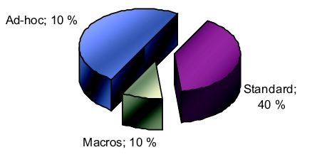 |
Spreadsheets should be handled differently depending on whether they are simple, standard, ad-hoc spreadsheets or whether they contain macros. The percentages are estimated values. An ad-hoc spreadsheet is characterised because it is only used once and if the result is to be saved, a signed copy of the printout is archived. Ad-hoc spreadsheets are used for investigations, to establish trends, to list tasks that are to be completed and for many other similar activities that are only performed once.
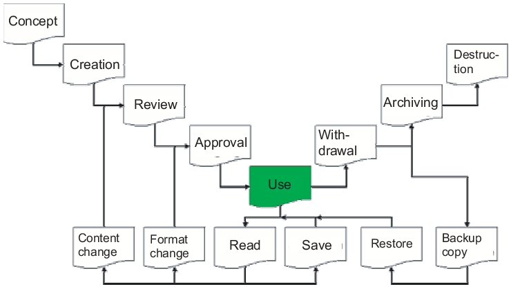
The following description explains the life cycle of a spreadsheet in accordance with the Good Practice and Compliance for Electronic Records and Signatures, Part 2, ISPE, PDA, December 2001. Each spreadsheet runs through a life cycle from concept to compilation, quality control and approval, through to its usage. It is then withdrawn, archived for the required retention period, and finally destroyed. The short life cycle of the spreadsheet consists of reading and storing. Content changes are subject to quality control and authorisation in accordance with a change management procedure to be defined, while format changes only require approval. Change management is described below (see chapter 9.F.7 Change management and error reporting). The quality control process can be carried out by the user in a similar way to a laboratory assistant rechecking a calculation. However, if the workflow requires that a superior position is always responsible for checking calculations, then the recalculation of spreadsheets should also be performed by this same person (figure 9.E-16).
A spreadsheet that is ready for use can also be retrieved from the archive and used again following a backup and restore process.
 |
An SOP for validation
The classification of spreadsheets should be defined in an SOP for the validation of spreadsheets, so that it is harmonised, consistent and traceable as far as possible. This also introduces a simple and uniform procedure, so that standard spreadsheets can be processed quickly. A user-friendly SOP should also contain forms (figure 9.E-17).
|
Table of contents for an SOP for the validation of spreadsheets |
|---|
|
|
Ad-hoc applications
Although they probably make up the majority of all applications used, ad-hoc spreadsheets should not be used for standard applications in the lab or in production. Ad-hoc usage means that a spreadsheet is used for a particular purpose and is then no longer used again. Applications may include:
- Summarising tasks
- Maintenance of to-do lists
- Tables of contact partners during inspections
- Analysis of experimental results in deviation handling
- Overview lists of outstanding complaints
- Management information
- Etc.
In short, spreadsheets are appropriate wherever a table is the suitable representation for handling a task. Quality assurance purists may argue that non-validated applications from the laboratory or production should be banned. However, a non-validated spreadsheet is still better and more traceable than corresponding manual analyses and data collections. In addition, the spreadsheet, just as all other deliverables, should be reviewed and signed.
Activity checklist
The first step in validation is the compilation of the activity checklist, which can be directly linked to roles and responsibilities. This forms annex 1 of the SOP for the validation of spreadsheets.
|
System name: |
CSV inventory no.: |
|||
|
Role |
Name |
Department |
Signature |
Date |
|
Author |
||||
Documentation is stored according to the validation registry (figure 9.E-18).
|
Completed |
Activity |
Comment |
|
|---|---|---|---|
|
Recording of the system in the CSV inventory |
According to SOP for the validation of spreadsheets |
||
|
CSV classification report compiled and approved |
|||
|
Perform risk evaluation |
According to SOP for risk evaluation |
||
|
Roles and responsibilities |
Annex 2 of the SOP for the validation of spreadsheets. |
||
|
System description |
Annex 3 of the SOP for the validation of spreadsheets. |
||
|
User requirements |
Annex 4 of the SOP for the validation of spreadsheets. |
||
|
Supplier assessment |
Only perform if obtained from a supplier |
||
|
Change management |
Specify which SOP is used for change management |
||
|
User training |
Documentation in operating office in accordance with training SOP |
||
|
The system contains custom-programmed macros. |
If macros exist, handle these according to general CSV class 5. |
||
|
Yes |
Mark with a cross if applicable |
||
|
If interfaces exist and are used, these must be taken into account in the validation in accordance with the level of risk. |
Risk evaluation and CSV classification must also include this information |
||
|
Compilation of the user SOP, if required |
If no suitable equipment instruction manuals, methods, or other SOPs exist |
||
|
Compilation of the system logbook or the equipment logbook (incl. PC) |
See SOP for equipment logbooks |
||
|
Implementation of logical security and backup of data Template (*.xlt) must be in directory .../EFFECTIVE/ and be equipped with write-protection. |
Can be described e.g. in the PC logbook or in other documents |
||
|
Compilation of the function test and maintenance SOP (virus protection) |
If necessary, otherwise reference to a general infrastructure maintenance SOP that would normally apply for networked computers. |
||
|
Completion of the validation registry (document list) |
Annex 5 of the SOP for the validation of spreadsheets. |
||
|
Creation of the validation report |
Annex 6 of the SOP for the validation of spreadsheets. |
||
Roles and responsibilities
Roles and responsibilities are established in accordance with the following form, which makes up Annex 2 of the SOP for the validation of spreadsheets.
|
System name: |
CSV inventory no.: |
||||
|
Role |
Name |
Department |
Signature |
Date |
|
|
Author |
|||||
Establishing roles for the validation (figure 9.E-19).
|
Role |
Name |
Department |
|---|---|---|
|
Person responsible for the system |
||
|
Validation team |
||
|
Quality assurance |
System description
The system description is filled out according to Annex 3 of the SOP for the validation of spreadsheets (figure 9.E-20, figure 9.E-21).
|
System name: |
CSV inventory no.: |
|||
|
Role |
Name |
Department |
Signature |
Date |
|
Author |
||||
|
Overview diagram |
It is recommended to draw a block diagram of the main system components and their connections. The software components must be assigned to the relevant devices. Users should also be represented: Which system components does the user operate? Alternatively, references can be made to suitable graphics in user manuals or equipment logbooks. |
|
Description of the system |
Tasks of the system. Integration into the laboratory process. Description of the most important functions. Short list of system components from the overview diagram (with reference to the equipment logbooks for exact assembly) Interfaces to other systems. Alternatively, references can be made to user manuals or equipment handbooks if they contain the required information. |
|
System limitations |
Which system components are included in the validation? Which system components are not part of the validation? For example, auxiliary devices. |
|
Report on the previous operation of the system |
Only to be filled out for retrospective validations; in prospective validations of new systems, enter "New system". Date of start-up Summary of experiences and risk evaluations so far: Special features, error rate and measures taken, if applicable. It is useful to include a reference to the equipment logbook (back-up and restoration of data) and - if applicable - a note that other risks (manipulation errors, system downtimes) are prevented by user training or through the use of validated methods. |
User requirements
User requirements of generally implemented standard analytical spreadsheets are usually derived from the requirements of the relevant analytical procedure and are not specific for the company. In this case, a reference can be made in this field to the user manual or to other equipment documentation that describes what is expected from this system. If necessary, specific user requirements must be extended.
The following notes apply:
- The user requirements form the basis for the system specifications and for the acceptance test.
- Ideally, a list of numbered user requirements should be created as part of a traceability matrix, in order to enable the unique assignment of the acceptance tests to be performed for the specific user requirements.
- If the system classification and risk evaluation show that ERES requirements (21 CFR Part 11) should be applied for the standard system, the resulting requirements for this must be listed.
- H/M/L in the Priority column means that a user requirement is weighted accordingly. H stands for High, M for Medium, and L for Low. In the acceptance test, the system must pass all the user requirements classified with H and fulfil the majority of M requirements, or the latter must be achievable using applicable alternative methods. No limit is determined for L.
- For systems with a low risk, the first table (see figure 9.E-23) can be used. For systems with a high risk (risk index ³55), the table "Description of user requirements with risk reduction" should be used.
The user requirements are drawn up according to annex 4 of the SOP for the validation of spreadsheets.
|
System name: |
CSV inventory no.: |
||||
|
Role |
Name |
Department |
Signature |
Date |
|
|
Author |
|||||
|
Person responsible for the system |
|||||
Description of user requirements.
|
No. |
Requirement |
Priority |
|---|---|---|
|
1 |
||
|
2 |
Add further lines if necessary. Delete excess lines. |
H/M/L |
Description of user requirements with risk reduction (figure 9.E-23).
|
No. |
Requirement |
Priority |
Risk |
Reduction |
Residual risk |
|---|---|---|---|---|---|
|
1 |
|||||
|
2 |
Add further lines if necessary. Delete excess lines. |
H/M/L |
H/M/L |
H/M/L |
Validation registry
The validation registry is filled out according to Annex 5 of the SOP for the validation of spreadsheets (figure 9.E-24).
|
System name: |
CSV inventory no.: |
|||
|
Role |
Name |
Department |
Signature |
Date |
|
Author |
||||
|
Required documentation according to CSV policy |
Current name of the document |
Storage |
Valid |
|---|---|---|---|
|
CSV policy and guidelines |
CSV policy and guidelines V.2.0 |
EDMS (electronic document management system) |
01.05.01 |
|
Inventory |
Inventory list of all equipment and systems |
Operations office |
Updated continually |
|
CSV classification report inventory no.: |
Classification report no. 120406_KLB Inventory no. 120406 |
||
|
Risk evaluation |
Risk evaluation 120406_RBW |
||
|
Validation plan |
SOP for the validation of spreadsheets |
||
|
Validation report |
Annex 6 of the SOP for the validation of spreadsheets. |
||
|
Validation registry |
Annex 5 of the SOP for the validation of spreadsheets. |
||
|
Supplier assessment |
Supplier declaration and/or audit report |
||
|
User requirements |
Annex 4 of the SOP for the validation of spreadsheets. |
||
|
System specifications |
Annex 3 of the SOP for the validation of spreadsheets. |
||
|
Development standards |
SOP for the development of spreadsheets |
||
|
Project change control SOP |
General departmental change control SOP |
||
|
Functional risk evaluation |
If existing |
||
|
Technical documents (for IT) |
|||
|
Test protocols |
Test against user requirements |
- |
|
|
Acceptance test documentation |
- |
||
|
Traceability matrix |
|||
|
System configuration basis |
SOE (Standard Operating Environment) |
||
|
SOP for backup and restore |
Ensured by the infrastructure. Reference to validation of the infrastructure. |
||
|
User SOPs |
Guideline 129 V 3.0 GMP training concept |
EDMS |
15. 12. 02 |
|
Change control SOP |
Training verification |
||
|
Security administration SOP |
List IQ documents |
||
|
SOP for archiving |
If necessary |
||
|
SOP for user training |
If no suitable equipment instruction manuals are available |
||
|
SOP for periodic review |
List supplier documentation (equipment manuals) |
||
|
Plan for system retirement |
Not applicable |
||
|
System retirement report |
Not applicable |
Validation report
The validation report is filled out according to Annex 6 of the SOP for the validation of spreadsheets.
|
System Name: |
CSV Inventory No.: |
|||
|
Role |
Name |
Department |
Signature |
Date |
|
Author |
||||
|
Owner |
||||
|
QA |
||||
Specific notes:
|
Deviations from the validation plan |
|||
|---|---|---|---|
|
Limitations |
|||
|
Open issue |
Responsible for processing |
Completion date |
|
|
Open issues |
|||
|
Add further lines if necessary. Delete excess lines. |
|||
9.E.7.3 Laboratory systems
The GAMP Good Practice Guide "Validation of Laboratory Computerized Systems" contains a detailed list of suggestions of how to classify the various equipment in a laboratory (figure 9.E-26).
|
GAMP Class |
GAMP 2 A |
GAMP 2 B |
GAMP 3 C |
GAMP 3 D |
GAMP 3 E |
GAMP 4 F |
GAMP 5 G |
|---|---|---|---|---|---|---|---|
|
Design |
To be calibrated if necessary |
Cannot be changed by users |
Configuration parameters are saved and used constantly. |
Proprietary configuration parameters, saved, administrated and used |
|||
|
Interfaces |
None or not in use |
Simple interface to one computer |
Many interfaces |
||||
|
Data processing |
None |
Outside the system |
Post-processing of raw data within the system |
Interactive |
|||
|
Results and electronic data storage |
No data generation |
Stored |
Processing of measured values and stored data |
||||
|
Raw data or test results are not further processed or saved. |
Raw data or test results are further processed or saved. |
||||||
|
Examples |
Oven, centrifuge, incubator, Temperature control in stability chamber, ultrasonic bath, glass washing machine |
Balance, pH meter, thermometer, Viscometer, conductivity measuring device, titrator, recorder, electrolyte analysis device |
NIR , GC , HPLC with console control, PCR particle measuring device, simple robotic system |
NIR, NMR, HPLC/GC with PC control, microplate reader, immunoassay |
HPLC with PC control and data recording, integration software, integrated robotic applications |
Commercial LIMS Proprietary data recording systems, Spreadsheets without macros |
Proprietary LIMS |
9.E.8 Dealing with existing systems (legacy systems)
Legacy systems are systems that require later validation. This subsequent validation is also known as retrospective validation.
In a retrospective validation, the advantages of validation are obviously not fully utilised, since this involves the collection and compilation of documents that are created as a natural consequence in a prospective validation during the software life cycle. For a legacy system, the system owner should ensure that the actual status is analysed, the deliverables are still produced, and the documentation is updated or created.
In the retrospective validation, at first glance it appears as if something has been forgotten, which is sometimes also the case. On the other hand, enhancement of the functionality may mean that validation becomes obligatory for a system that previously did not require validation (see chapter 9.D.2 Risk indexes). In addition, new regulatory requirements can also cause a system that did not require validation to change its status.
9.E.8.1 Analysis of the actual status
The inclusion of available documentation and the collection of existing information pave the way for planning tasks that are still required in order to achieve the validated status. A table of the expected deliverables that should be available for a prospectively validated system can be adjusted for the retrospective validation.
It can be restricted to the minimum deliverables that are required by the authorities, and which could also be useful when replacing the legacy system with a new system. The following list shows which points should be documented for a legacy system and compares them in relation to the documentation for a new system. The "New" column shows which deliverables would be required for new systems. "Existing" refers to deliverables that should be available for legacy systems. The final column shows which points in a standard operating procedure should be regulated (figure 9.E-27).
|
Documentation list |
New |
Existing |
SOPs |
|---|---|---|---|
|
Validation plan |
X |
X |
|
|
Risk evaluation |
X |
X |
|
|
Validation report |
X |
X |
|
|
Supplier assessment |
Possible |
Possible |
|
|
Configuration basis |
X |
X |
|
|
Change requests |
X |
|
|
|
Physical safety |
X |
X |
X |
|
Logical security and system access |
X |
X |
X |
|
Backup and restoration |
X |
X |
X |
|
Archiving |
X |
X |
X |
|
Proof of training |
X |
X |
X |
|
User requirements |
X |
||
|
System specifications |
X |
X |
|
|
Technical specifications |
X |
||
|
Development procedures |
X |
||
|
Program. source code, configuration data |
X |
X |
|
|
Test protocol |
X |
X |
|
|
Traceability matrix |
X |
||
|
Unit and integration test |
X |
||
|
Installation test - IQ |
X |
||
|
System test - OQ |
X |
||
|
Service level agreements |
Possible |
Possible |
|
|
Operating instructions |
X |
X |
X |
|
Technical instruction manuals |
X |
X |
|
|
Acceptance test - PQ |
X |
X |
|
|
Implementation plan |
X |
||
|
User SOPs |
X |
X |
X |
|
User manual |
X |
X |
|
|
System description |
X |
X |
|
|
Periodic review plan |
X |
X |
X |
|
QA release |
X |
X |
X |
9.E.8.2 Experience report
The experience report collects the key data for the system from operation.
- System name, manufacturer, version number
- Short description of system
- How long is the system in operation?
- Data diagrams, interface description
- Errors or failures that have occurred with the system
- No. of users in the system
The experience report is written by the system operator and should be signed by the system owner and quality assurance. It is an important source for proving system reliability.
|
Summary: Validation involves planning, execution, and reporting. This includes the definition of responsibility and organisation, the creation of a validation policy, inventory, and a detailed discussion of the validation plan and report. A validation plan for computerised systems contains a system description, the regulation of responsibilities, the workflow of the validation activities, and the points that must be documented throughout the validation process. For specifications (technical specification, user requirements), it is important to agree, internally and with any suppliers, precisely what is included in which document. Good specifications are characterised in part by easily measurable requirements for which test cases can be created to test with relatively little extra work. The applications are tested throughout the stages of the integration test, system test, and acceptance test using various test methods, of which the most important are the positive function test and the negative function test. The validation report is a short summary of the validation activities that have been carried out successfully. In some circumstances, it may include a list of open issues that can still be processed after start-up. In the retrospective validation, the actual status is recorded and an experience report is established. If data is transferred from a legacy system into a newly validated system, this should be performed in a careful, planned, and traceable manner. |
Requirements management tools
www.jiludwig.com/Requirements_Management_Tools.html (Stand 20. 03. 2007).
Guy Wingate: Computer Systems Validation: Quality Assurance, Risk management and Regulatory Compliance for Pharmaceutical and Healthcare Companies, CRC Press, 2004 .
