|
Here you will find answers to the following questions:
|
|
Definition of DQ (EU GMP Guideline, Annex 15) - Design qualification |
|---|
|
"The documented verification that the proposed design of the facilities, systems and equipment is suitable for the intended purpose." |
Design qualification is the documentation of the planning phase, including the decision making for the equipment. Design qualification takes place before the equipment is constructed. The risk analysis (see chapter 6.B.6 Risk analysis) is often part of the design qualification. The earlier risks can be recorded and evaluated, the sooner their minimisation can be taken into consideration in the equipment construction phase.
With the design qualification, the conformity of the equipment planning with certain requirements is reviewed. To this end, the requirements laid out in the user requirements are compared with the specifications compiled by the supplier (technical specifications) and confirmed in writing. The design qualification consists of the elements specified in figure 6.D-2.
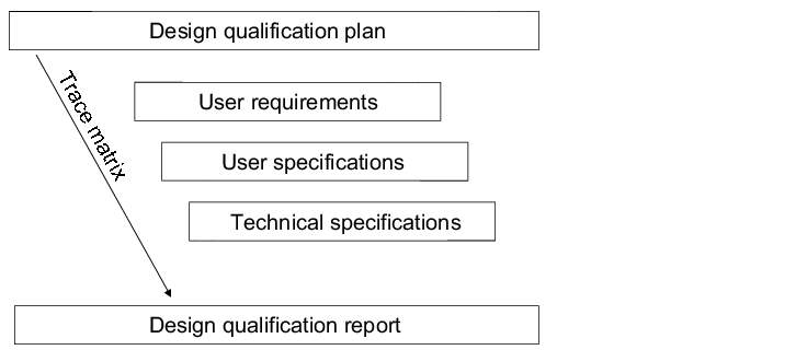 |
For simplification and for a clearer arrangement of the comparison between the user requierments and the technical specifications, a simple trace matrix can be used. The traceability characteristic means consistent referencing between user requirements, specifications and test cases. This makes it possible to trace cross references between the specified elements (traceability). To this end, the user requirements are to be provided with unique numbers, so that referencing is possible. Figure 6.D-3 shows a possible trace matrix.
|
UR no. |
UR text |
TR no. |
TR text |
Spec. no. |
Specification |
Test number |
Comments |
|---|---|---|---|---|---|---|---|
|
UR 1.1 |
Use of rust-free stainless steel |
TA 1.1.1 |
1.4571 or higher is to be used. |
SP 1.1 |
1.4435 |
IQ 1.1 |
Material is high quality and is therefore accepted. |
|
TA 1.1.2 |
The material must be verified. |
SP 1.2 |
3.1B Attestation |
IQ 1.1 |
- |
||
|
SP 1.3 |
Material confusion test |
IQ 1.1 |
to be carried out with documentation |
||||
|
UR 1.2 |
Smooth surface |
TA 1.2.1 |
Roughness depth |
SP 1.4 |
Hand cut with grain 400 |
IQ 1.2 |
- |
|
SP 1.5 |
Surface roughness measurements with record |
IQ 1.2 |
Record and number of test points is to be defined. |
For each user requirement (UR), there must be at least one technical requirement (TR). This is a 1:n relationship. For each technical requirement (technical specification) there must in turn be at least one specification. The project manager can use the trace matrix in the design qualification to show clearly that all user requirements have been taken into account. In addition, he can use it to check if the technical specifications are complete and if the technical implementation corresponds to the requirements. As a last step, the trace matrix can be used in the test plan compilation to prove that all user requirements have been tested (example shown in figure 6.D-3).
An example of how the user requirements and technical specifications can be structured is shown below. For a further example of design qualification, see chapter 6.D.1.2 Example: Washer).
6.D.1 User requirements (user specifications)
The purpose of the user specifications is to define the user's pharmaceutical and technical requirements for the equipment (= user requirements). This ensures that the equipment is suitable for the later application and that the equipment can be used to manufacture a product that is in line with the specifications under GMP-conform conditions. The user specifications describe what, why and for what reason.
The configuration of the equipment must reflect the current state-of-the-art. Therefore, all technical, but also all legal requirements (GMP, equipment safety, employee protection) must be described and taken into account in the user specifications. The information in the user specifications can be used as a basis for tenders, offers and/or contracts.
Figure 6.D-4 shows the typical contents of user specifications.
|
Components of user specifications |
|
|---|---|
|
Project description |
Brief description of the project and the project objective |
|
Legal requirements |
GMP rules Technical facility safety Safety at work Environmental protection |
|
Requirements for equipment |
Construction plans Diagrams (e.g. R & I, measuring and control technology, electrics, hydraulics/pneumatics, utilities, plumbing, assembly plan) Usage procedures Maintenance procedures Spare parts list Conformity declarations |
|
Environmental conditions at the planned place of installation |
Permissible floor load Available utilities and their layout Potential influencing factors (e.g. dust, vibrations) Clean room requirements Room conditions (temperature, air humidity including regulation areas) |
|
Safety devices |
Electrical and mechanical locks Electrical protection classes Electrical circuit breakers, safety valves, fault reports, alarms Pressure reduction, non-return valve |
|
Utilities |
Utilities including connection values and required performances Cleanliness requirements |
|
Technical dimensions and weights |
Installation dimensions Weight of the overall installation |
|
Material quality |
Compatibility certificates for product contact surfaces Certificates for purchased components (e.g. software) Requirements for the surface properties (e.g. roughness) Required surface passivation (inertisation) |
|
Constructive requirements |
Utilities supply and filter classes Control equipment and systems for plant data acquisition Sampling devices Extension possibilities (e.g. additional docking points and additional interfaces) |
|
Equipment cleaning |
Cleaning procedures Cleaning processes (manual, CIP) Cleansing agent |
|
Performance data |
Batch size (maximum, minimum) Maximum and minimum process parameters (e.g. stirring speed, pressure, temperature, time) Mechanical and electrical performance requirements |
|
Controls |
Automatic process control Requirements for computer validation Control and documentation (e.g. screen, instruments, plant data documentation paper/electronic) |
|
Calibration, maintenance |
Definition of the type and working range/sensitivity of measuring points requiring calibration Maintenance and calibration plan Maintenance agreements |
6.D.1.1 Example: Reaction vessel
There are different ways in which user specifications can be structured.
Figure 6.D-5 shows a solution for a reaction vessel.
|
User specifications using the example of a reaction vessel |
|---|
|
Contents 1. Project description 2. General requirements 3. Functional requirements 4. GMP requirements 5. Machine requirements 6. Technical documentation 7. Factory Acceptance Test/Site Acceptance Test 8. Responsibilities 9. Authorisation |
|
1. Project description This reaction vessel is to be used as a new facility in the "sterile production of liquid dosage forms" project by Pharma GmbH. |
|
2. General requirements The following guidelines by Pharma GmbH are to be observed: 2.1 Guideline for the control and electro-technical equipment of industrial machines and facilities Version 1.0 of 04.08.1999. In particular, the prescribed electrical and electronic components are to be taken into consideration. 2.2 Accident prevention procedures guideline 2.3 EMC guideline 2.4 At least Ex-Zone 2 |
|
3. Functional requirements 3.1 100 l batch volume 3.2 Data on minimum fill volume 3.3 Respiratory filter housing for XY filter insert 3.4 Vessel suitable for +6/-1 bar 3.5 Double jacket in the frame area, +6/-1 bar 3.6 Flange with PT 100 temperature sensor with display/Ex 3.7 Manhole approx. DN 400 with flap screws 3.8 Observation window approx. DN 100 with illumination/Ex 3.9 TC flange for manometer, safety valve, filter and reserve 3.10 Ex-impeller stirrer |
|
4. GMP requirements 4.1 Requirement for controlled area in clean room class C 4.2 Spray ball/dip tube in an aseptic design for cleaning via CIP 4.3 Floor outlet valve in aseptic design, drive and outlet brought forward to the container wall, outlet pipe gradient at least 3% 4.4 All valves/fittings used in aseptic design 4.5 Floor outlet valve can be fully emptied 4.6 Vessel and valves can be sterilised via SIP 4.7 Respiratory and sterile filters can be sterilised via SIP 4.8 Easy cleaning possible |
|
5. Machine requirements 5.1 Two sliding handles for transport 5.2 Compressed air impeller stirrer with revolution display 5.3 Four pharma-compliant antistatic wheels, two guide rollers and two fixed rollers 5.4 Material from W 1.4435/AISI 316L 5.5 Inside of container electro-polished RA < 0.5 mm 5.6 All seals made of pharma-compliant Teflon 5.7 Type-tested safety valve 5.8 TC flange (Triclover) |
|
6. Technical documentation The following documents must be provided: 6.1 Technical specification. (Comment: The manufacturer and type of all components must be specified. Before beginning execution, the technical specification must be approved by the contract provider.) 6.2 Detailed plan 6.3 Equipment/Facility description/Operating instructions with overview of the technical data in German and English 6.4 Energy and utilities supply including operational parameters 6.5 Filter certificate 6.6 Material certificates of the product contact parts or list of the parts, e.g. valves, seals, inner walls, stirrers if they come into contact with the product 6.7 Technical data sheets for all components including measuring and control technology, e.g. for temperature sensor, manometer, stirrer or motor, spray ball/dip tube 6.8 Environmental conditions to be complied with 6.9 German maintenance instructions with intervals in operating hours) 6.10 Cleaning instruction |
|
6.11 List of spare parts/wear parts 6.12 List of cables 6.13 Terminal plans 6.14 Schematic or operating diagrams (electricity) 6.15 Calibration report for factory calibration 6.16 EMC record 6.17 Certificates (e.g. according to ISO 900x) 6.18 Conformity declaration |
|
7. Factory Acceptance Test/Site Acceptance Test 7.1 Factory Acceptance Test (FAT) Acceptance of the facility takes place at the supplier's premises, adapted to the project conditions at Pharma GmbH. All versions/measures from the technical specification must work correctly according to the user requirements. Detailed prechecking of the operator's documentation is carried out by the supplier. 7.2 Site Acceptance Test (SAT) Complete installation and start-up of the facility by the operator Personnel training of the user on-site Complete documentation |
|
8. Responsibilities for the engineering area Plant engineer |
|
9. Authorisation The user specifications for the 100 l reaction vessel were checked and released: |
|
Position Date Signature |
|
Compiled on: Person in charge of equipment ................ |
|
Test: Plant engineer ................ |
|
Test: Plant manager |
|
Released on: Head of Production ................ |
6.D.1.2 Example: Washer
|
Elements of the facility specification |
|---|
|
In the following, the specification for a washer is shown as an example:
Preliminary remark
This specification describes the minimum delivery scope for a facility that cleans, disinfects and dries equipment intended for use in the pharmaceutical industry. This document does not provide a comprehensive or complete description of the system to be delivered. Instead, it defines a minimum technical standard and refers to standards and specifications applicable in this case.
Direct references to standards and rules and regulations
The following standards and rules and regulations must be taken into consideration during the design and construction of automatic washers. This also applies to specifications not stated here that are relevant to the construction of the facility.
- EU GMP Guideline of good manufacturing practice for medicinal products
- Current Good Manufacturing Regulations and Guidelines (cGMP) of US Food and Drug Administration (FDA)
- Pertinent specifications by the Federal Institute for Drugs and Medical Devices (BfArM)
- European Pharmacopoeia
- DIN standards
- VDE guidelines
- VDI 2890: scheduled maintenance; instructions for the compilation of maintenance and inspection plans
- Trade association accident prevention regulations
Description of facility
- Functionality: automatic cleaning, drying and disinfection of pharmaceutical equipment. Cleaning is carried out using water with varying qualities to which cleansing agent is added depending on the programme step. The final rinse must be carried out using purified water.
- Description of procedure: A standard cleaning procedure as shown in figure 4.E-2 should be possible. The tenside-based cleaners are specified. Water and air temperatures must not exceed X °C.
- Accessories: washing baskets
|
Rinsing programme |
|---|
|
Mechanical components
- Full drainage of machine and pumps; no exposed heating elements; variable partitioning of internal compartment
- Pharma-compliant version characterised by:
- use of material 316L for all surfaces and pipes coming into contact with media,
- use of diaphragm valves and tri-clamp connections,
- dead volume-free and fully drainable installation,
- prevention of mixup or reverse contamination and
- use of a validatable process control and machine documentation.
- Two programmable liquid metering pumps for cleaning fluids with metering monitoring function.
- Drying with high-performance blower, HEPA filter in the drying circuit not required. Aspiration of the drying air from the production room with filtering according to clean room class D. Release of the drying air via the roof.
- Condensate drainage in venting line to prevent backflow contamination
- Dimensions
- Materials: washing compartment and inner face of door: 316L (alternatively 1.4401). Cladding material: 1.4301. The materials used for seals and tubes must correspond with the recommendations of the US Food and Drug Administration (FDA). Works certificates for the above materials must be included in the delivery.
Controlling
- Freely programmable control (microprocessor control or PLC). The programme should be structured in a modular fashion. Headings for the individual programme modules must be provided.
- Plain text display in German
- Display of washing programme, current programme step, temperature of washing compartment and remaining running time.
- It must be possible to print out the programmes and all their parameters (if required, printer to be connected).
- Self-diagnosis, programme and malfunction statistics
- The control should incorporate a memory that accommodates several (>10) wash programmes that may be called up individually.
- The machine must stop if the preset parameters are not complied with. The operator should then be provided with the reason why the process was cancelled. When the machine is restarted, the entire wash programme must be repeated.
Process monitoring
- Monitoring of the following process parameters with display option and limit value monitoring with alarm or machine stop.
- Temperature of rinsing water
- Pump pressure (circulatory pump)
- Drying temperature
- The sensors must be readily accessible and removable for calibration purposes (cable length) and it must be possible to calibrate these with the entire measurement chain.
- Dosage monitoring of detergent pumps
- Sampling tap for water samples
- Error display for important functions and utilities
- A connection that enables the machine to be regularly requalified must be provided. For example, a connection that can be used to log the progress of the relevant parameters during a rinsing cycle via an on-site chart recorder.
Supply of energy and utilities
- Connections for the following water types: purified water, 65 °C, connection to loop provided by customer; drinking water both warm and cold.
- Drainage via open funnel siphon to prevent backflow contamination
- Electrical connection: 400 V/50 Hz
- Steam connection
- Connection to exhaust line provided by customer
Constructional prerequisites
The equipment must be installed in a wash room. The particle and microbiological loading of the room corresponds to clean room class D. The target room temperature is 20 °C +5/-2 °C, at 50 % r.F.. Data on the required limits at the installation location (temperature, rel. humidity, electrostatic and magnetic influencing parameters) must be supplied.
Installation, start-up, acceptance tests
The scope of delivery includes:
- Free delivery and placing at site (supervision of placing as minimum)
- Complete assembly and start-up incl. test operation
- Instruction of operating personnel
- Necessary acceptance tests: the contract giver reserves the right to audit the manufacturing, programming and quality assurance at the premises of the contract acceptor.
The pre-delivery check, otherwise known as the Factory Acceptance Test (FAT), at the manufacturer's premises guarantees the necessary manufacturing quality and ensures that the function tests are carried out.
The final acceptance, otherwise known as the Site Acceptance Test (SAT), by the contract giver takes place at the installation location once assembly and start-up have been completed and the operating personnel have been instructed. It must be verified that
- the delivery of the facility is complete and correct,
- the documentation is complete,
- the installation is correct,
- the cleaning and auxiliary programmes specified by the operator and also the safety devices are functioning faultlessly,
- the locks and alarms are functioning faultlessly,
- the installation and function of the measuring equipment is correct and
- the initial calibration of the sensors carried out at the installation location (if carried out by contract acceptor) is correct
The basis for the pre-delivery check and the site acceptance test is a reference programme to be compiled by the supplier according to the specifications of the contract acceptor containing all elements of the subsequent cleaning task. This programme also serves as the basis for carrying out function tests within the scope of the operational qualification.
Furthermore, three cleaning cycles with contaminated equipment are to be carried out to assess the success of the acceptance test using the following criteria:
- Visually clean / analytically clean
- Visually dry
- Surface quality of the materials washed
- Analysis of the cleansing agent residues (see chapter 8.E.2 Calculation of cleansing agent residues)
Documentation, validation, qualification
For the technical documentation to be supplied for qualification of the facility, see the Basic documents table (see chapter 4 Facilities and Equipment, figure 3, figure 4, figure 5).
6.D.2 Technical specification
The technical specifications represent the transformation of the requirements laid out in the user specifications into the binding technical specifications and requirements for the supplier (technical requirements). In certain cases, a detailed proposal can replace the technical specifications (e.g. in the procurement of HPLC facilities as equipment off the shelf).
User requirements and technical specifications are important documents for the legally prescribed acceptance after delivery of the equipment.
Figure 6.D-8 shows an example of the required specifications for a reaction vessel.
|
User specification for a reaction vessel |
|---|
|
Compilation |
|
Function/name in block letters Date Signature Head of procedure processing (Kessel) |
|
Authorisation |
|
Function/name in block letters Date Signature User |
|
Authorisation |
|
Function/name in block letters Date Signature Head of Production |
|
1. Scope of delivery 2. Use of the equipment 3rd Fulfilment of the requirements 3.1 Directives and standards 3.2 Functional requirements 3.3 GMP requirements 3.4 Mechanical requirements 3.5 Technical documentation 3.6 The following is not included in the documentation 3.7 Room temperature 3.8 Cleaning the facility 3.9 Precision 3.10 Calibration 3.11 CE certification |
|
1. Scope of delivery The delivery consists of: 1 x 100 l vessel The construction data is listed in the certificates and in the pressurised container drawing. Equipment for the above-mentioned part: Ventilation filter housing Lower outlet valve 25 Lower outlet valve 15 Manometer Safety valve Temperature sensor Observation window Dip tube Control box for temperature display and observation window illumination Magnetic stirrer (air-driven) Control box for magnetic stirrer |
|
2. Use of the equipment The vessel should be used for all the usual, liquid, pharmaceutical productions. It is particularly suitable for all applications in which drainability and aseptic quality (design for CIP/SIP) are of significance. This special container and the associated equipment were classified as "Ex" suitable. The container jacket can be used for checking the temperature of the batch. The batch temperature is displayed on the front of the control box. The container has an observation window and illumination. The light can be switched on via a switch on the box. The container is cleaned in-line with the installed cleaning ball. The container is equipped with a housing for the sterile filter for ventilation and pressure regulation. |
|
3rd Fulfilment of the requirements |
|
3.1 Directives and standards Electricity: European Directive EN 60 204-1, including the low voltage directive 73/23/EEC and electromagnetic compatibility, is complied with. The machine guidelines are complied with. The components fulfil the EMC Guideline Electromagnetic Compatibility 89/336/EEC. |
|
3.2 Functional requirements Volumes: the working volume is 100 l. The capacity is 110 l. Minimum working volume: 10 l Ventilation filter: filter type FTS140 G23 Design pressure: the inner container and jacket have a design pressure of +6/-1 bar (g). Temperature transmitter type Pt 100m and display type D122.A are installed. Transmitter and display are EEx class 1b IIC T6. The transmitter has a temperature drift of less than 0.1%/10 K and a linearity below 0.1%. The calibration certificate is located in the final documentation. The cover hatch with a diameter of 250 mm and joint bolt is welded. The observation window DN 100 is installed with EEx-classified illumination. TC flanges for manometer, safety valve, filter and replacement are included. |
|
3.3 GMP requirements The equipment was designed so that it is suitable for category A rooms (in accordance with cGMPs). The cleaning ball reaches all areas of the inner surface during CIP. Cleaning ball/dip tube are designed for aseptic conditions (CIP /SIP). Cleaning ball/dip tube NP1007824 series no.: __________ is designed for container ID no:_______ with a pressure drop of 1.5-1.8 bar at 2500 l/h. Lower outlet valve type valve 25 with extended discharge drawing no.: NP1010706 (gradient 3%). The valve is provided with a manual jet outlet and is installed in the bottom of the container. The valve can be drained fully. The lower outlet valve type valve 15. The valve is provided with a manual jet outlet and is used as a sampling valve. The valve can be drained fully. The installed equipment is designed to be aseptic. The cleaning ball is designed for effective cleaning of the container. The container and equipment, including the ventilation filter, can be sterilised by SIP. The container can be cleaned externally. The vent filter is designed for SIP. |
|
3.4 Mechanical requirements Two transport handles on the container. The mixer is designed for SIP. There are four nylon wheels, two can be turned and have brakes and two are fixed. The container is provided with an earth cable plate. The inner container is Ra < 0.5 mm and is electro-polished. CE labelling on the container The material of the product contact parts is WN 1.4435/AISI 316L. Material certificates are in the final documentation under Chapter 3 Vessels. Material in jacket and legs is WN 1.4301/AISI 304 Material in the insulation: mineral wool Material in the seals: |
|
3.5 Technical documentation The following are included in the documentation: Container construction drawing Lists of materials and container certificates Container approval certificates (design approval and manufacturing approval), including design data List of components and spare parts Component documentation: filter, manometer, safety valve, temperature transmitter, etc. The user guide and maintenance manual for the valve is in German. Electrical drawings: layout and circuit diagram Certification of conformity with CE conformity Certification of conformity of the material Quality certificate Test documents for containers and cleaning ball function Certificate for the safety valve setting Conformity letter that confirms that all product-contact components are designed for CIP/SIP. Required specifications |
|
3.6 The following is not included in the documentation Layout / installation drawing List of utilities data / operating data List of product-contact materials List of excipients Quality certificate according to ISO 900x |
|
3.7 Room temperature The room temperature for the facility is specified in the corresponding data sheet. |
|
3.8 Cleaning the facility External cleaning is carried out in accordance with the customer's standard procedure. Internally, the container is cleaned with a cleaning ball (see cleaning ball documentation for further information). The cleansing agents to be used depend on the product produced in the container. |
|
3.9 Precision For the precision of the manometer and temperature transmitter as well as the display, see the respective data sheets. |
|
3.10 Calibration Calibration of the transmitter is not part of the scope of delivery. |
|
3.11 CE certification EMC is fulfilled through the selection of approved components and by carrying out design and installation in accordance with the guidelines. EMC testing of the entire unit is therefore not necessary. |
|
Summary To avoid surprises, the equipment must be carefully planned and exactly specified (user requirements = user specifications). The supplier undertakes to accurately observe and implement the customer's requirements (technical requirements = technical specifications). The conformity of the user specifications and the technical specifications is checked during design qualification. The content of the user specifications and technical specifications is illustrated using examples. |
