5.E Operation of water supplies
|
Here you will find answers to the following questions:
|
5.E.1 Procedure to reduce microbial counts
Despite the high quality demands made on the implementation and design of ultra pure water generation facilities and ultra pure water storage systems and loops, it cannot be ruled out that bacteria, viruses or spores will gain access to such a system. For this reason, regular samples are taken and tested for organisms (see also chapter 5.D.7.1 Microbiological tests for pharmaceutical water). Measures for reducing the microbial count should generally be carried out at defined time intervals as preventative actions. A distinction is made between sanitisation, sterilisation and disinfection.
5.E.1.1 Sanitisation
During sanitisation different methods are used that enable a widespread, if not complete, reduction in the microbial count. However, the result of sanitisation cannot guarantee complete freedom from germs (unlike sterilisation). With regular, preventive sanitisation, the formation of biofilms and an exceedance of the microbial count limits can be prevented effectively.
Heat sanitisation
Heat sanitisation is carried out with hot water at a temperature of more than 80 °C (usually around 85 °C). To do this, the ultra pure water circulating in the loop is heated with a heat exchanger to the prescribed sanitisation temperature and is maintained at the sanitisation temperature for the prescribed period of time. After sanitisation, the heated water is either also cooled with a heat exchanger (hot/cold combination), or by the addition of hot and then fresh cold ultra pure water. Most bacteria occurring in ultra pure water are already killed at a temperature of 80 °C and with a corresponding length of time the agent is left to work, so that sanitisation, if carried out regularly, is an effective, preventive measure for avoiding biological fouling of the system and the formation of biofilm. For systems that are hot stored, we also speak of self-sanitisation, as a temperature of more than 80 °C is constantly complied with here. For the piping system, it must be ensured that the expansion that occurs during heating can be compensated for (natural compensation of thermal expansion through symmetrical bends (expansion bends) and simple angle bends). No components fitted in the system may be damaged by the sanitisation temperature.
Cold sanitisation
Cold sanitisation of ultra pure water storage systems and loops usually means sanitisation with ozone. With ozonised systems, the storage container is continuously kept in ozone. The ozone in the ultra pure water is destroyed with a UV emitter in the ring supply. An ozone measuring instrument behind the UV emitter monitors that there is no more ozone in the system up to the limit of detection (5 ppb). Sanitisation of the entire ring system is now possible by switching off the UV emitter and allowing the ozonised water to flow through the entire loop. The ozone measuring instrument is now used to monitor that the minimum ozone concentration defined for sanitisation is not undershot during the entire dwell time.
In practice, ultra pure water storage systems and loops are often regularly sanitised over night or on weekends for several hours with a concentration of 50 ppb to 100 ppb and thus good results are achieved. The exact procedure in terms of the sanitisation interval, ozone concentration and sanitisation duration must be specified by each operator individually for the respective facility. The only thing left to note here is that the ozone concentration should not be set too high, as ozone with an increased concentration also increasingly attacks the elastomers of the seals and measuring technique on the facility (e.g. EPDM) - and good sanitisation results can already be achieved with ozone concentrations of 50 ppb to 100 ppb and a correspondingly longer sanitisation time. It is important during sanitisation with ozone to ensure that the ozone concentration in the entire system remains above the limit. This can be guaranteed by monitoring the reverse flow of the system, e.g. with an additional ozone measurement. Figure 5.E-1 contains information on the ozone concentration and dwell time at which bacteria is killed.
|
Ozone |
Bac. subilis |
Staph. |
Micrococcus |
Ps. |
Serratia |
Pc. |
|---|---|---|---|---|---|---|
|
0.025-0.05 μg/l |
180 |
60 |
120 |
180 |
180 |
60 |
|
approx. 0.1 μg/l |
120 |
40 |
90 |
120 |
120 |
40 |
|
approx. 0.2 μg/l |
50 |
20 |
40 |
90 |
60 |
20 |
|
1.0-2.0 μg/l |
20 |
10 |
10 |
20 |
15 |
10 |
|
4.8-5.0 μg/l |
1 |
1 |
1 |
1 |
1 |
1 |
5.E.1.2 Sterilisation procedure
Sterilisation means making an object (system) completely sterile. The standard procedure from the European pharmacopoeia uses banked up steam (pure steam) for 15 minutes at 121°C. To do this, pure steam is fed into the storage system and loop and flows through the piping system and the containers. At all low points in the system and for longer pipes in certain intervals, condensate drains must be provided to drain away the condensate that occurs. At least at these low points, temperature recorders must be installed to monitor and document the sterilisation temperature, to check that no condensate was in the low points during sterilisation and thus prevented sterilisation at these points. The storage containers on systems that are to be sterilised must have a pressure resistance that corresponds to the pure steam pressure of the sterilisation temperature (see chapter 5.F Pure steam systems). For the piping system, it must be ensured that any expansion that occurs during heating can be compensated for (natural compensation of thermal expansion through symmetrical bends (expansion bends) and simple angle bends) and that no components fitted in the system can be damaged by the sterilisation temperature.
In practice, however, ultra pure water storage systems and loops are rarely sterilised with pure steam, as the constructive and energetic effort is very high. Usually, sanitisation (hot or cold) is sufficient to keep an ultra pure water storage system and loop sterile in the context of the prescribed limits.5.E.1.3 Disinfection
Chemical disinfection of ultra pure water systems is only recommended if (preventive) microbial reduction cannot be carried out using other methods (ozone, hot water, clean steam). Hydrogen peroxide or peracetic acid is used as the disinfection agent. It must be noted that the rinsing of the disinfectant can be very time-consuming on storage systems and loops (depending on the capacity of the water purification). Pre-configured products based on hydrogen peroxide or peracetic acid are supplied by different manufacturers.Disinfection with hydrogen peroxide, for example, is carried out for water treatment systems that cannot be sanitised with hot water due to their design and membranes. The use of ozone is usually ruled out for water treatment systems, as the reverse osmosis membranes, for example, are not compatible with ozone and are damaged by it.
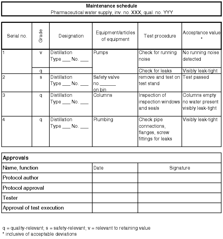
5.E.2 Maintenance of a water supply
During normal operation, a pharmaceutical water system must be continuously reviewed and regularly maintained in order to retain the qualified status. To this end, it must be noted that the facility is subject to technical wear and tear and the measuring points can deviate from the actual values. In order to combat these influences, regular maintenance on the facility and calibration of the measuring points should be provided for. The documentation of these measures helps maintain the qualified status.
A maintenance system can be constructed from two components that are linked with each other. First, the individual technical operations for each maintenance process are established. These are based on the maintenance procedures recommended by the manufacturer of the facility, as described in the operating instructions. Other necessary maintenance procedures can be derived from the environmental conditions and the peripheral facilities. The maintenance procedures can be established by the operating engineer and then released by the user of the facility (see figure 5.E-2). The location of the facility on which the maintenance work is to be carried out must be clearly defined to avoid any confusion. The individual work steps for maintenance are also described accurately, so that another technical employee can carry out maintenance at the same level. The individual maintenance work is documented and released. For each maintenance event, a maintenance interval is defined which prescribes the period until the next maintenance of the same kind. It is possible to choose different maintenance intervals for the same part of a facility, as some parts have to be maintained more frequently than others.
 |
The second component of the maintenance system is a schedule for the individual maintenance work. Each maintenance event is given a due date for execution, which is then repeated depending on the interval, e.g. every three months, twice-yearly or annually. This schedule must also be used to document when exactly the maintenance must be carried out, if the measure has been carried out on time or with a delay or if the maintenance was cancelled (more information in chapter 4.H Maintenance).
The maintenance records must document successful execution as well as any negative results and measures for reconstitution of the qualified status. Bear in mind that the water supply has articles of equipment
- that are significant for the qualified status,
- that are used to guarantee safety of the facility for life and limb,
- that the facility requires in order to work, but which are not quality-related for the product.
Thus, the maintenance work can be split into three categories:
- Quality-relevant maintenance
- Safety-relevant maintenance
- Value-maintaining maintenance
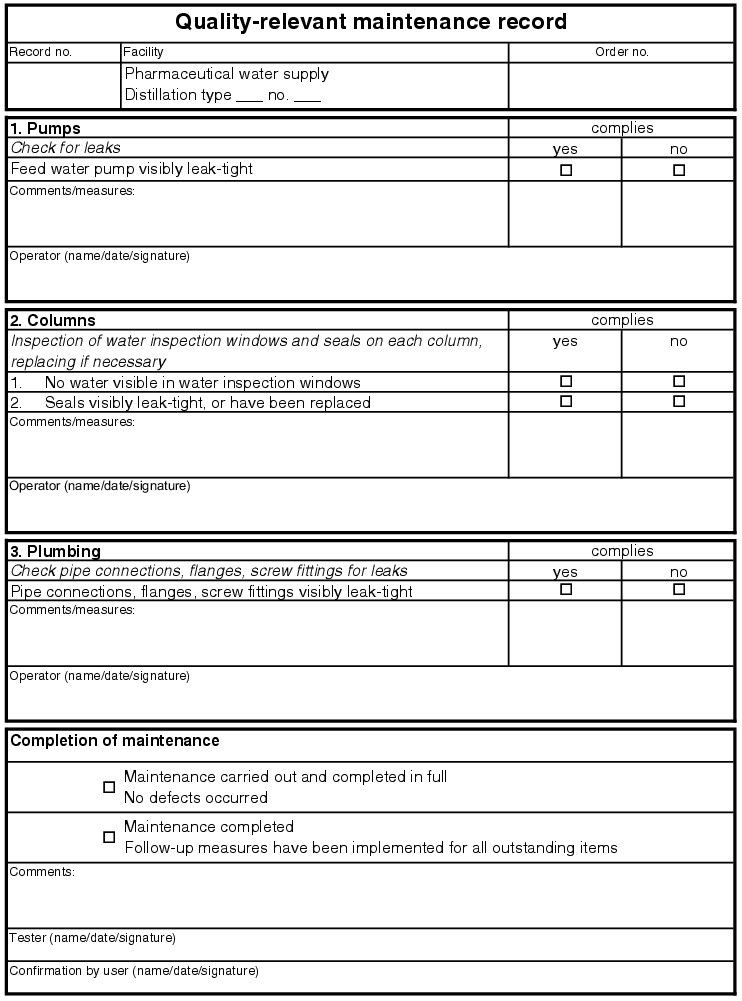
5.E.2.1 Quality-relevant maintenance
For all quality-relevant articles of equipment on the pharmaceutical water supply, the same type of maintenance must be carried out. According to the maintenance SOP XYZ, this maintenance must be carried out in a period of at most X weeks and execution is to be documented in the maintenance record.
In good time before the maintenance deadline for quality-relevant maintenance, the user of the facility is to be informed of the planned activity so that the facility can be made available for the work. After submission of the maintenance record, in which all steps are described, any spare parts and excipients for maintenance are to be provided. These must be in the same quality and of the same type as the original parts (see parts list from the supplier, qualified spare parts).
Before execution, an entry must be made in the log book for the facility/equipment, referring to the maintenance request. Then maintenance is to be carried out immediately and documented in the record. Maintenance points which pass and fail are to be noted accordingly. Measures must be defined for the points which failed and carried out immediately, if possible. Once these are done, a new test must be carried out using the maintenance record. If the measures cannot be implemented immediately, the facility or accessory must be repaired (repair note for documentation). If this is necessary, the facility must remain out of service until completion. After maintenance is carried out, another entry must be made in the log book and the facility is returned to the user.
The maintenance records can be released by a tester and the user, so that any manufactured product can be assessed. In the worst case, the user must take into account impacts on previously manufactured product. The released records are stored according to the document systematic and the time until the next test starts running (see figure 5.E-3).
 |
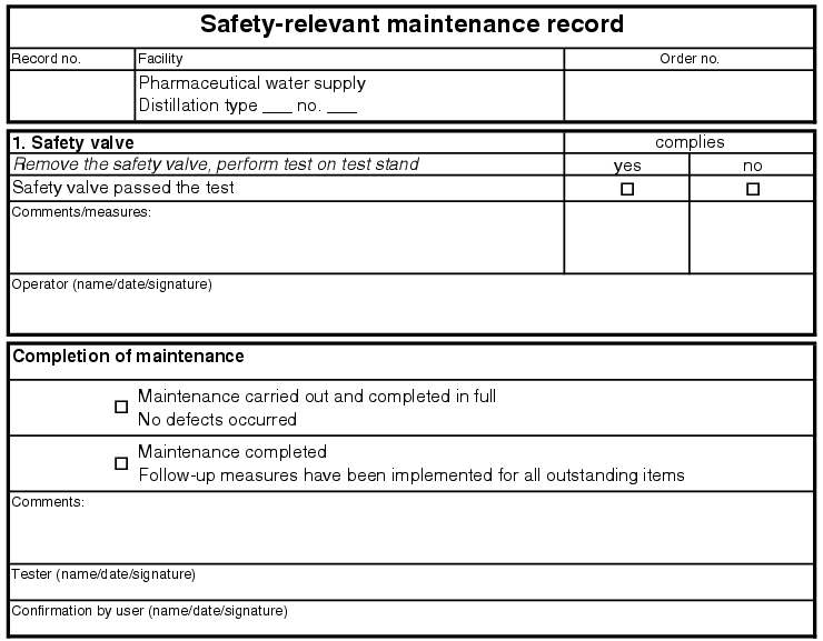
5.E.2.2 Safety-relevant maintenance
The procedure for safety-relevant maintenance is the same as for quality-relevant maintenance. This maintenance is used to document safe operation of the facility for life and limb and not to prove the quality of the product (see figure 5.E-4).
 |
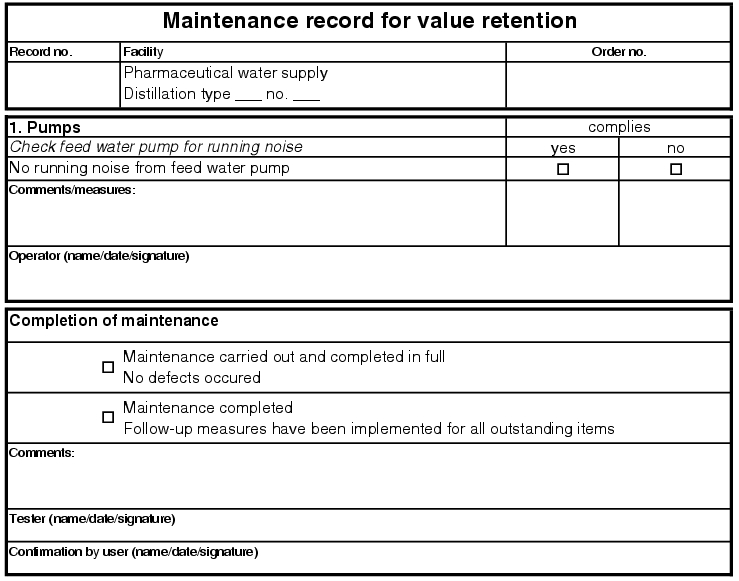
5.E.2.3 Value-maintaining maintenance
The so-called value-maintaining maintenance is also to be carried out with proof or a maintenance record, but can be processed in a longer period of time and can be omitted for quality-relevant or safety-relevant maintenance. This maintenance can be cancelled at any time by the user of the facility if the utilisation of the facility requires this (see figure 5.E-5).
 |
5.E.3 Calibration of measuring systems
Calibration of the measuring points is of extreme importance, as it is only with the correct values that the status of the facility can be accurately interpreted. Therefore, it is absolutely necessary to carry out calibration of quality-relevant measuring instruments just as regularly as the maintenance work. For this reason, it is advisable to record the calibrations in the maintenance system and process and document them there according to the same procedure.
For the water supply, the parameters specified in figure 5.E-6 are quality-relevant and their measurement is thus absolutely necessary.
|
Quality-relevant parameters |
|---|
|
For the entire water system, from generation of purified water and WFI to distribution in cycles, the temperature of the water is crucial, as microbial growth can be prevented at high temperatures.
The next important measurement is the determination of the flow in the loops and during manufacturing, as this can prove that the water is flowing turbulently in the system for the entire residence time. Depending on the system usage it may also be necessary to obtain a turbulent flow during water withdrawal. Turbulent flow can be used to prevent sediment in the pipes, biofilm, etc. (chapter 5.C.1.1 Flow rate and turbulent flow).
Next, the conductivity of the water is crucial as this increases as the amount of salts and impurities in the system increases. If the limits for WFI or purified water are exceeded, the water quality is not adequate. To determine the quality of the water, the TOC value (Total Organic Carbon) measurement must be used.
In order to produce purified water and WFI, it is absolutely necessary to guarantee a certain pre-pressure in the system. This is controlled with pressure gauges. In addition to these measurements, which can be registered continuously, i.e. round the clock, there are also discontinuous measurements as part of process validation. With the continuous measurements, the pressure in the system can be proven and documented at any time. The fact that the correct values are determined at all times can only be guaranteed through regular calibration, i.e. inspection of the measuring sensors.
5.E.4 Change control
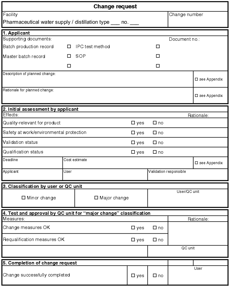
Maintenance and calibration checks guarantee the qualified operation of the facility in its installed status. These measures do not provide for any changes or extensions to the facility. All spare parts used during maintenance and calibration checks are described in the parts lists as original spare parts. There are no type changes and thus also no performance changes on the facility. If this pattern is deviated from in any way, a change request (see figure 5.E-7) must be made, which describes the change to the facility and estimates the consequences of the change (see chapter 19.C Change control and chapter 6.H.4 Maintenance of the qualified status).
Two different systems can be used for storage using the document system. First, it is possible to store the change request complete with all new documents in a folder in the system. In this case, however, this change request must be referred to in all other folders in the system. The old documents affected by the change are to be marked as invalid in the folders. This guarantees that the current documents are taken into consideration and that the old documents are not used accidentally. The second option seems more time-consuming, as all new documents of the change request are maintained in the correct documentation folders, but must be provided with a new version number, so that it is clear that it is the latest version that is valid. In addition, reference to the change request must be made in the documents, so that it can be proven that the change has been executed in full. The change request should contain a list of all newly created documents and their location in the documentation. These two procedures provide complete cross-referencing
 |
5.E.4.1 Major and minor changes
Minor changes to the water supply are documented but do not require requalification of the facility. Minor changes to the water supply are usually non-quality-relevant facility components and equipment or spare parts of a new type or by a different company than mentioned in the parts list, but with the same performance data as the original spare part.
Example of minor change: Replacement of a pressure increase pump by company X for a pump by company Y with the same pump characteristics. There will certainly be material certificates and new operating instructions for the new spare part, which must be included in the document system for the water supply. Due to the identical pump characteristics and the downstream pressure measurement, it can be easily checked if the required pressure is reached in the supply line. Requalification of the loop is not necessary in this case. If quality-relevant system components are replaced or extensions are made on the water supply, such as construction of an additional subloop, these measures are to be classified as major changes in the change request, and requalification of the system section or the entire facility is to be carried out.
Example of major change: Change to the pre-pressure in the loop by fitting a pressure increase pump with a greater performance level. Due to the changes in the loop, the flows and withdrawal situations from the loop change. In addition to the new documentation of the pump, which in turn has to be maintained in the document system, quality-relevant statuses in the loop also change. Whether or not these correspond to the requirements in the original user requirements can only be clarified through requalification.
5.E.5 Requalification
In order to maintain the qualified status of the water supply even after years of operation or after a quality-relevant change, this status may have to be reviewed. This is done through a reduced repetition of the original qualification, as this is where the procedure is defined, and you have already gained experience during the initial qualification. The extent to which reductions should be approved compared with the initial qualification depends on the operating processes carried out in the meantime (e.g. maintenance, change management). If requirements have changed, the technical specification can no longer be used completely as the basis for qualification. Therefore, a user requirement can be used instead, in which all the current changes to the facility have been compiled. The subsequent requalification of the facility using the qualification procedure described in chapter 5.D Qualification of water supplies, i.e. planning, execution and testing according to DQ, IQ and OQ, then finally PQ is based on this.
5.E.5.1 After major changes
If major or quality-relevant changes are made in the context of a change request, at least the affected facility component or the special equipment must be requalified. In the change request for quality-relevant changes (major change), the measures for requalification must be described by the applicant in addition to the planned changes to the facility. Then, release by the user and validation officer must be obtained and QA must be involved. Quality assurance should check the change measures and assess the measures for requalification. The measures must then be carried out in the individual steps of the qualification and recorded. A requalification report completes the measures and documents the status of the facility component or the equipment after the change is carried out.
5.E.5.2 After defined interval
If the facility is not adapted after several years of operation and if no changes are made through new spare parts, requalification may nonetheless be advisable after a certain period of time. So, for example, requalification can be planned and carried out with an interval of five or ten years. To this end, new qualification protocols and user requirements must be compiled. Then the DQ and subsequently the IQ, OQ and PQ may have to be carried out and documented. Due to the many years of positive operating experience with the facility, some test points can be omitted or shortened with a note about the results of continuous monitoring. Requalification is to be completed with a qualification report and with its release by the user. The measures of maintenance, calibration, change control and requalification accompany the entire life of a facility and thus guarantee that the technical status of the facility is maintained at all times in line with the desired requirements.
5.E.6 Decommissioning/uninstalling
If the water supply is to be decommissioned, certain rules have to be complied with. For example, before decommissioning, a plan of the individual steps must be compiled. The first point is important: Will the facility be dismantled for scrap or is it to be recommissioned elsewhere? During disassembly for reconstruction, the individual components must be cleaned and dried after shutdown and separated from each other at suitable interfaces. These interfaces must be accurately described and labelled so that the facility can be correctly assembled again at the new location. All components are to be checked for impurities, standing water and other defective properties before assembly. A complete qualification of the facility must be carried out. Particular attention must be paid to the PQ and monitoring, as impurities that are overlooked in the facility mean that the product cannot be produced with the desired quality. If deficiencies are discovered, the entire facility must be cleaned and sterilised again. If the facility is to be scrapped, the components can be taken apart with slightly less care, but the actual shutdown and technical documentation of the facility must be handled carefully.
5.E.6.1 Shutting down the water supply
If the water supply is fully decommissioned, it must first be ensured that the pharmaceutical production of market goods is stopped. Then the shutdown of the subloops must be documented, as well as the draining of the on-site storage containers, the shut down of the loop with storage containers and the shut down of the water production facilities. Only after draining and guaranteeing that no more water is in the facility and that no more facility components and equipment are tempered, can the next step of decommissioning be started.
5.E.6.2 Disassembly work on the facility
Disassembly work can begin now. Please note that clean room conditions can be lifted for the period of disassembly. The area is to be declared a construction site and indicated as such. It must then be ensured that all media feeds are securely sealed (key valves) and the supply lines are capped. This will prevent serious accidents through steam, compressed air or other media. In addition, the electrical supplies must be shut down and secured (extraction of electrical fuses). This can prevent electrical accidents during disassembly. Then the electrical wires must be measured and released before disconnection - they must not be capped due to the risk of an electrical short circuit. These measures must be logged and checked, in order to rule out any risks for the disassembly team. Now the individual mechanical components of the facility can be removed and checked for environmental impurities. After ascertaining their safety, the components can be scrapped. The area around the location of the facility and the pipes must be cleaned and the environment requirements restored. To this end, holes in walls and the ceiling must be closed and cleaning arranged. The clean room conditions are to be restored through the room ventilation systems and the status documented.
All the above-mentioned measures are to be documented and maintained in the documentation system for the water supply. In this way, proper disassembly can be proven and the new status of the area documented. The measures should be planned before execution and released by the validation officers. Tests for general personal safety or for environmental safety can be recorded in disassembly records. The disassembly manager should compile a final report on the disassembly carried out.
The entire documentation of the water supply, including the disassembly documents, is to be archived in the case of scrapping. Provided product from the facility could be on the market (calculated according to the stability of the final market product), it must be possible to review the documentation for the batches produced and the technical documentation of the facility. In order to achieve a greater level of safety, an archiving time of ten to fifteen years is often assumed. The life cycle of a facility ends after this period.
|
Summary Regular sanitisation of the water generation system and the storage system and loop is the only way of preventing the formation of biofilm. A distinction is made between thermal sanitisation, when the facility is rinsed with hot (> 80 degree Celcius) water, and chemical sanitisation, with the example of H2O2 as the disinfectant. |
