| Here you will find answers to the following questions:
|
5.D.1 Introduction
Qualification of water supplies follows the principles described in detail in chapter 6 Qualification. Plans, records and reports are created for the design qualification, installation qualification, operational qualification and performance qualification phases. Risk analysis is also part of an earlier phase of qualification (DQ). The test points and special features for a water supply are dealt with below.
The water treatment system is the core of pharmaceutical production, as the generated water flows directly into the product or at least comes into contact with the product. Qualification is therefore of the almost importance and is a fixed part of inspections.
The main test points are
- Material proof
- Proof of the weld quality
- Design of the flanges used and aseptic connections
- Electrical components
- measuring and control technology
- Role
- Monitoring
- Documentation
The following directives (recommendations) deal specifically with pharmaceutical water:
- FDA: Guide to Inspections of High Purity Water Systems (see chapter D.3 Guide to Inspections of High Purity Water Systems)
- EMEA: Note for Guidance on Quality of High Purity Water for Pharmaceutical Use (see chapter C.8 Note For Guidance on Quality of Water for Pharmaceutical Use )
Below, the qualification phases are described based on the example of water purification of potable water through purified water to water for injection (see figure 5.D-1).

|
As we are dealing with a complex facility with many individual components (see chapter 5.B Generation of pharmaceutical water and chapter 5.C Distribution and storage of pharmaceutical water), there should be a separate qualification master plan that lists all activities.
In contrast to other equipment qualifications, extensive performance qualification (PQ) is indispensable.
5.D.2 Risk analysis
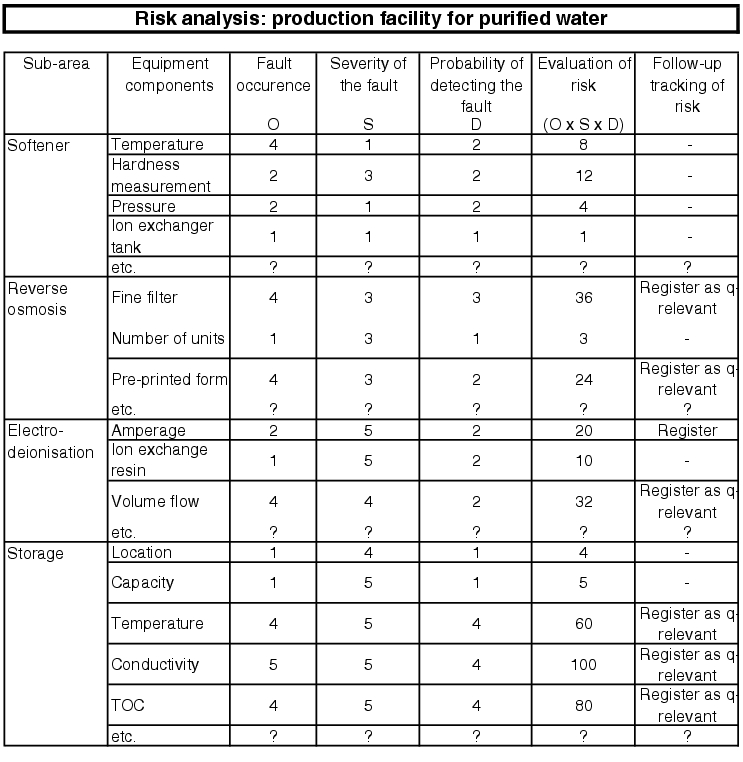
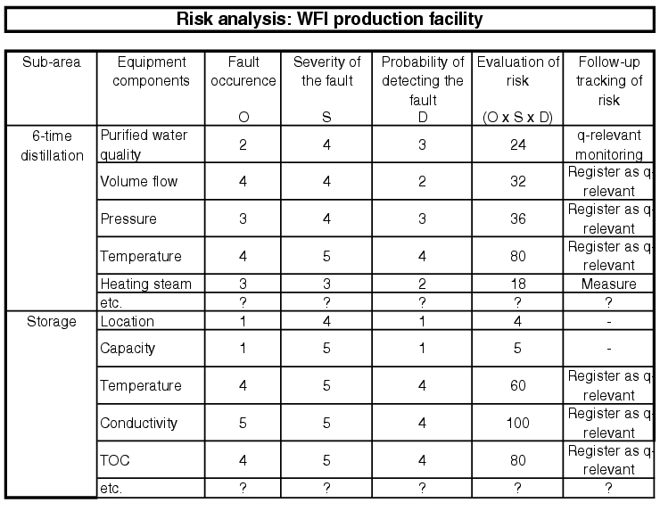
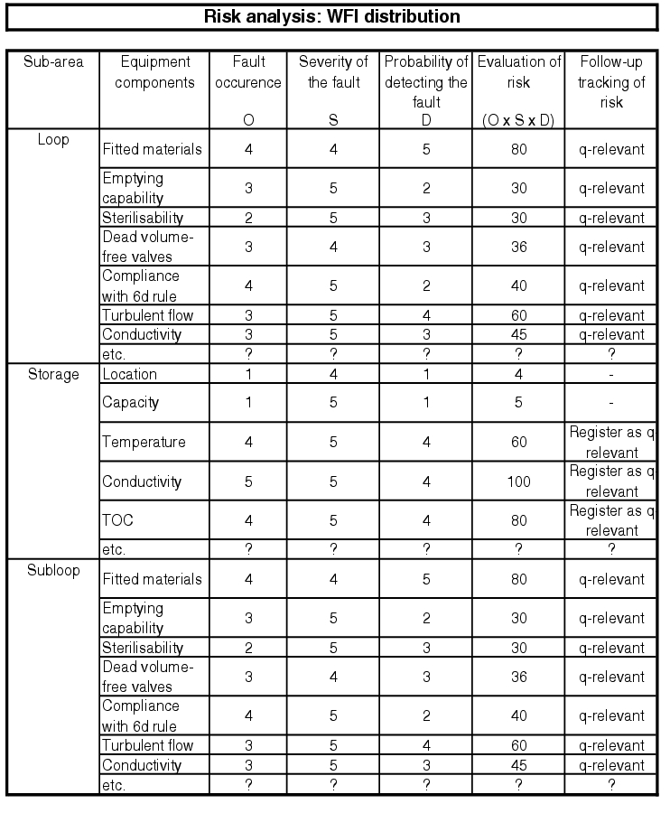
In order to efficiently carry out risk analysis for an extensive pharmaceutical water system, the facility should be subdivided and the smallest parts of the facility taken into consideration, e.g. according to the FMEA principle (see figure 5.D-2 to figure 5.D-6).
More information is given in chapter 6.B.6 Risk analysis and chapter 10.D Methods of risk management.

|
|
|

|
|
5.D.3 Design qualification
The qualification of a water supply shown here as an example and in extracts should explain and clarify the procedure. The specific execution of qualification of a water supply requires an exact definition of all requirements and the resulting tests.
5.D.3.1 User requirements
The basis for the first test stage of qualification is the user requirements (see figure 5.D-7): User Requirement Specification, in which the operator describes his requirements. For more information see chapter 6.D.1 User requirements (user specifications).
| User requirements for a pharmaceutical water supply |
|
|---|---|
| Project description |
A pharmaceutical water supply should be established for the production of WFI from potable water. The WFI should be available continuously 24/7 and should be routed to different production equipment via a loop for purified water (cycle). The WFI is incorporated in the final product and is used to clean the production equipment. |
| Legal requirements |
The legal provisions for Europe and the USA must be complied with (GMP Design). The technical facility safety and safety at work should be guaranteed according to the state-of-the-art. Requirements for environmental protection must be taken into account. |
| Requirements of the equipment documentation |
Documentation, such as engineering drawings, parts lists, software documentation, measuring and control documentation set-up plans, assembly plans, assembly instructions, spare parts, operating instructions, maintenance/repair and interface descriptions |
| Environmental conditions at the planned installation location |
The permissible floor load is X kg/m2. At the installation location, the potable water connection is available and an area of 25 m2 is available. The room is in the clean room area D and already meets the requirements. |
| Safety equipment |
The electrical connections must be fused. Assembly must be carried out so that there is no risk to life or limb; in particular, hot surfaces must be insulated. If limits are undershot, an alarm must sound in the control room. Containers must meet the pressurised container requirements. Safety equipment for avoiding excess pressure must be available. |
| Utilities |
Potable water connection with X m3/h, steam connection with Y t/h without additives in the steam, special salt for softener (discontinuous). There is an electrical connection with a capacity of Z kW/h. Oil-free and dry compressed air is required with a pressure of X bar. In addition, cooling water must be available with a flow volume of 500 kg/h. |
| Material quality |
All materials that come into contact with the product must have an FDA marketing authorisation and be supplied with a 3.1B certificate. Metals that come into contact with the product must be designed as 316.L steels and supplied with a peak-to-valley height of <0.8 mm. All purchased components must be certified. The facility's control unit or the computer programme must be manufactured according to current quality standards and must be validated. |
|
Constructive |
The facility must be equipped so that purified water and WFI is automatically, continuously produced with the required parameters. The required media for the facility are to be transferred to the facility with the defined qualities (list per medium). Filters are not to be used in water loops, as they act as microbial collection points. Terminal filters in dead end piping (6d rule) for transferring the water to production equipment are used with the quality of high efficiency particulate air filters type XY. A sufficient amount of sampling equipment is to be planned and drawn in the installation scheme and released. The facility should be controlled via a central operating point and all malfunction indications and alarms should also be shown here. All measuring values and reports should be registered in the long-term. The data should be available so that it can be archived. |
| Equipment cleaning |
All facility surfaces are to be designed so that they are easy to clean and any splash water drains away. For cleaning instructions, see SOP XXXX. It should be possible to sterilise the facility and to clean containers with CIP systems (Cleaning in Place). |
| Performance data in routine operation: |
The water supply should produce 3.5 m3/h purified water and 1.5 m3/h WFI. As of a quality of purified water, a minimum temperature of 80°C should be complied with. The water pressure must be at least 2.5 bar. The conductivity for WFI must not exceed 2.7 mS/cm. |
| Calibration, maintenance: |
The calibrations and maintenance work are to be carried out in accordance with the valid SOP XXX. The supplier's maintenance recommendations are to be taken into account. |
5.D.3.2 Technical specification
The technical specification translates the desires and requirements of the user into technical specifications (see also chapter 6.D.2 Technical specification). This can be compiled by the internal technology department, the possible supplier of the facility or by an external engineering firm. If a specific type is preferred, it is recommended to provide the external supplier with forms for compilation of the technical specification (see figure 5.D-8).
For the qualification of existing facilities, the subsequent compilation of user requirements and technical specifications is not usually necessary. Instead, reference is made to the existing documents. If no usable documentation is available, the GMP requirements for the facility are to be written down in a document. This can contain, for example, the user's requirements and the technical specifications of the existing facility. This document should be verified by quality assurance.
| Form: technical specification for the pharmaceutical water supply |
|||||
|---|---|---|---|---|---|
| Task of the facility: |
|||||
| Requirements in terms of function and equipment: |
|||||
| Integration/connection with existing systems: |
|||||
| Proof of qualification: |
Proof of qualification must be provided by an installation check, and by an implementation and operational check (IQ,OQ). These checks inspect the correct installation and the requirements of the function of generation of WFI. The checks are carried out using test records. Proof of the WFI quality must be provided in the course of validation and then by routine sampling. |
||||
| Location conditions for buildings/rooms: |
|||||
| Medium |
Temperature |
Pressure |
Flow volume |
Acceptance |
|
| Potable water |
|||||
| Quality |
|||||
| Cooling water |
|||||
| Quality |
|||||
| Steam |
|||||
| Quality |
|||||
| Condensate |
|||||
| Quality |
|||||
| Compressed air |
|||||
| Quality |
|||||
| Electr. connections |
|||||
| Facility / equipment articles: |
|||||
| Requirements in terms of apparatus and equipment: |
|||||
| Basic material |
|||||
| Rated pressure |
|||||
| Generation of purified water |
|||||
| WFI generation |
|||||
| Container |
|||||
| Container ventilation |
|||||
| Heat exchanger |
|||||
| Pipes: |
|||||
| Seals: etc. |
|||||
| Requirements of the process: |
|||||
| Process parameters |
Alert limit |
Alarm limit |
in accordance with USP |
||
| Temperature |
|||||
| Pressure monitoring |
|||||
| Reverse flow quantity |
|||||
| Conductivity |
|||||
| etc. |
|||||
| Requirements of automation: |
|||||
| Requirements of the process: |
|||||
| Checkpoint |
Acceptance criterion |
Unit |
in accordance with USP |
||
| Appearance |
Clear, colourless |
||||
| Odour |
Odourless |
||||
| Conductivity |
|||||
| pH value |
|||||
| etc. |
|||||
| Requirements of the intermediate or final product: |
|||||
| Checkpoint |
Acceptance criterion |
Unit |
in accordance with USP |
||
| Appearance |
Clear, colourless |
||||
| Odour |
Odourless |
||||
| Conductivity |
|||||
| pH value |
|||||
| etc. |
|||||
| Requirements of documentation: |
|||||
| Regulatory environment: |
|||||
| Technical guidelines: |
|||||
| Internal guidelines: |
|||||
| etc. |
|||||
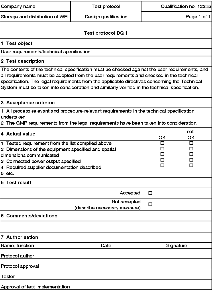
5.D.3.3 Test protocol
An extract of a test protocol is illustrated in figure 5.D-9.
| DQ test protocol |
||||
|---|---|---|---|---|
| Pharmaceutical water supply / Inv.No. X / Qualification No. YYY |
||||
| Seq. no. |
Test item |
Test feature |
Acceptance value |
Record no. |
| 1 |
User requirements, technical specification |
1. Requirements of the user requirements available in the technical specification |
All process-related and procedure-related requirements available in technical specification |
DQ 1 |
| 2. Implementation of the GMP requirements |
The GMP requirements from the legal requirements have been taken into account. |
|||
| 2 |
Quality test |
Carried out |
Pass |
DQ2 |
| 3 |
Acceptance |
Carried out |
Pass |
DQ3 |
| 4 |
etc. |
etc. |
etc. |
etc. |
| Approvals |
||||
| Name, function |
Date/signature |
|||
| Record approval |
||||
| Tester |
||||
| Approval of test execution |
||||
5.D.3.4 Test record
To check the technical specification against the user requirements, the GMP requirements are described in a test record in keyword form. During the DQ, these points are processed in sequence. If deviations occur, they are documented in the field provided (figure 5.D-10).
|

|

|
5.D.4 Installation qualification
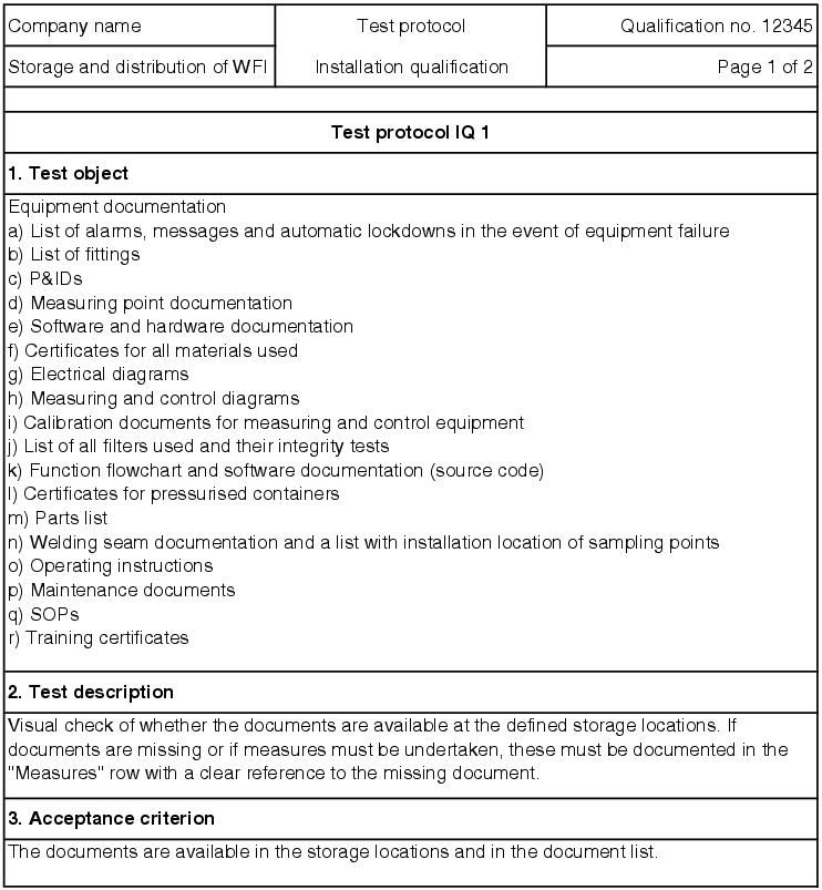
The aim of the installation qualification is to check the facility in terms of the assembly, conformity of the components, compliance with the guidelines described in the user requirements and technical specification and legal requirements as well as the completeness of the documentation (see chapter 6.E Installation qualification (IQ)).
A test protocol contains, the points mentioned in figure 5.D-11, for example. After the plan is released, the tests must be carried out and recorded. After the installation qualification has been passed, the operational qualification can start. If there are open measures and deficiencies, these must be processed during the installation qualification. If the elimination of open measures has no influence on the operational qualification, this can also be carried out during the OQ (e.g. missing labelling of pipes).
| Test points for installation qualification |
|
|---|---|
| General points: |
|
| Facility-specific points: |
|
5.D.4.1 Facility documentation
The facility can only be started up if the documentation is available, the operating personnel trained and the proof carried out that the facility is continuously operated correctly.
The documents required for set-up and operation should be listed in the technical specification. In addition, all operating instructions, SOPs and other documents for operation of the facility must be available at the right time. Likewise, all documents that define and describe the qualified status of the facility must be procured. For a complete water supply, the documents specified in figure 5.D-12 are required, amongst others.
| Technical documentation for water supplies |
|---|
|
The manufacturer of the facility is responsible for the procurement of the documentation required for set-up and start-up. The requirements on the user are listed in the user requirements so that everyone in the project speaks the same language regarding the documentation. These documents must be complete and correct and are checked during the IQ.
Operating instructions
All operating instructions must be complete, correct and easily understandable. Normal operation must be described, as well as measures for maintenance and in the event of failure of the facility (repair instructions). Training for the staff should be derived from the operating instructions (operating personnel and maintenance personnel). The instructions should have a table of contents so that they can also be used as a reference work.
Standard operating procedures (SOPs) and applicable regulations
All standard operating procedure which affect the water supply or apply for the facility in operation, are to be listed and named and must be taught to the staff concerned. Other internal instructions, which affect the water supply directly or indirectly, as well as general behaviour in the area or in the company must also be taught and named.
Documentation system
The technical documentation should be stored using a standardised system developed for all facilities in order to help internal staff and inspectors and external service providers to find their way. Figure 5.D-13 gives an example.
| "Pharmaceutical water supply type XY" documentation system |
|
|---|---|
| 1 Project basics |
1.1 User requirements 1.2 Technical specification 1.3 Applications to authorities 1.4 Qualification protocol 1.5 Calculation principles 1.6 Drafts 1.7 Ordering process 1.8 Acceptance |
| 2 Drawings and measuring and control documentation |
2.1 Engineering drawings 2.2 parts lists 2.3 Software documentation 2.4 measuring and control documentation |
| 3 Assembly |
3.1 Set-up plans 3.2 Assembly plans 3.3 Assembly instructions |
| 4 Operation |
4.1 Training 4.2 Spare parts 4.3 Operating instructions 4.4 Maintenance/repair 4.5 Changes 4.6 Safety checks |
| 5 Interfaces |
5.1 Building interfaces 5.2 Media interfaces 5.3 Facility interfaces 5.4 Loop interfaces |
| 6 Qualification |
6.1 Design qualification 6.2 Installation qualification 6.3 Operation qualification 6.4 Qualification report 6.5 Transfer protocol |
| 7 Other points that appear necessary |
|
| 8 Decommissioning |
|
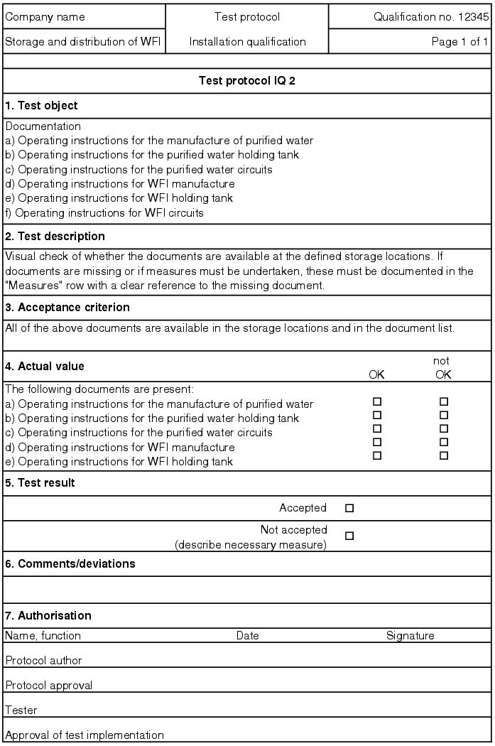
5.D.4.2 Test protocol
In the test protocol for installation qualification, the individual points for checking the execution and installation of the water supply are listed as in the DQ test protocol. All critical components are checked for correct assembly, correct set-up position and correct wiring. Not only the physical assembly of the facility is checked, but also the documentation of all components, which were supplied by the manufacturer (see chapter 5.D.4.1 Facility documentation). The IQ tests are described using test features and acceptance criteria. The scope of the test is established and refers back to the test records with which the tests are carried out (see figure 5.D-14).
| IQ test protocol |
||||
|---|---|---|---|---|
| Pharmaceutical water supply / Inv.No. X / Qualification No. YYY |
||||
|
Seq. |
Test item |
Test feature |
Acceptance value incl. the permissible deviations |
Record |
| Documentation |
||||
| 1 |
Facility documentation |
Availability |
The documents are available at the storage locations and in the document list |
IQ 1 |
| 2 |
Operating documentation |
Availability |
The documents are available at the storage locations and in the document list |
IQ2 |
| 3 |
Maintenance, repair documentation |
Availability |
The documents are available at the storage locations and in the document list |
IQ3 |
| etc. |
||||
| Materials/surfaces |
||||
| 5 |
Certificates for materials |
1. Availability |
The certificates are available at the storage locations and in the document list |
IQ5 |
| 2. Conformance |
The metal materials used for parts that come into contact with the media are 316L or 316Ti. |
|||
| 6 |
Certificates for seals and membranes |
1. Availability |
The certificates are available at the storage locations and in the document list |
IQ6 |
| 2. Conformance |
The materials used cannot be destroyed by disinfectants. All media-contacting components are resistant to steam up to 135 °C. |
|||
| 7 |
Proof of peak-to-valley height |
1. Availability |
The documents are available at the storage locations and in the document list |
IQ7 |
| 2. Conformance |
The peak-to-valley height must meet the requirements. |
|||
| 8 |
Sterilisability of the system |
Media connections |
Media connections for sterilisation with pure steam are available and documented on the installation scheme. |
IQ8 |
| etc. |
||||
| Installation test |
||||
| 10 |
System drainability |
Availability |
The entire system can be drained, i.e.:
|
IQ10 |
| 11 |
Entire system |
Accessibility |
The facility installation is assembled so that a good and non-dangerous accessibility for maintenance and repair work and sampling is guaranteed. |
IQ11 |
| 12 |
Installation schemes |
Conformity |
Installation and documentation agree |
IQ12 |
| 13 |
Parts list |
Conformity |
The facility components and installation parts match the parts list. |
IQ13 |
| 14 |
Fittings |
Fittings in lines that come into contact with media are: |
IQ14 |
|
| 1. Rated pressure |
Designed with at least 10 bar rated pressure |
|||
| 2. Installation |
Installed corresponding to the direction of flow |
|||
| 3. Installation |
Installed so that it can be drained |
|||
| 4. Implementation |
Dead volume-free |
|||
| 15 |
Container |
1. Drainability |
Drainable |
IQ15 |
| 2. Safety |
Equipped with a safety valve |
|||
| 3. Bleed pressure |
Bleed pressure in accordance with maximum permissible operating excess pressure |
|||
| 4. Implementation |
Safety valve is sealed and aseptic. |
|||
| 5. Integrity of the water system |
Maintenance and repair work is possible (in-/offline) without damaging the integrity of the water system |
|||
| 6. Condensate collection |
No condensate can collect in the ventilation and deaeration lines or in the filters. |
|||
| 7. Fill level monitoring |
The fill level of the container is monitored. |
|||
| 8. Vacuum strength |
Container is vacuum-tight or equipped with electrically monitored bursting disks. |
|||
| 16 |
Sampling equipment |
Conformity |
Sampling must be possible at the following points
|
IQ16 |
| etc. |
||||
| Welding |
||||
| 18 |
Fixed welding |
Conformity |
Only the required welding procedures (TIG orbital welding) were used. Manual welding only where absolutely required. Welds are visually ok. |
IQ18 |
| 19 |
Detachable connections |
1. Connection type |
Implementation as aseptic connections |
IQ19 |
| 2. Free from defects |
The connections are free from defects and leak-tight. |
|||
| etc. |
||||
| Measuring and control technology |
||||
| 21 |
Measuring and control index |
Conformity |
The measuring points listed in the measuring and control index must match the measuring points marked on the installation scheme. |
IQ21 |
| etc. |
||||
| Electricity |
||||
| 23 |
Operating circuit diagram |
1. Conformity |
The electrical installation of the facility matches the circuit diagram. |
IQ23 |
| 2. Legibility |
Labelling matches the requirements in the circuit diagram and is legible at all points. |
|||
| etc. |
||||
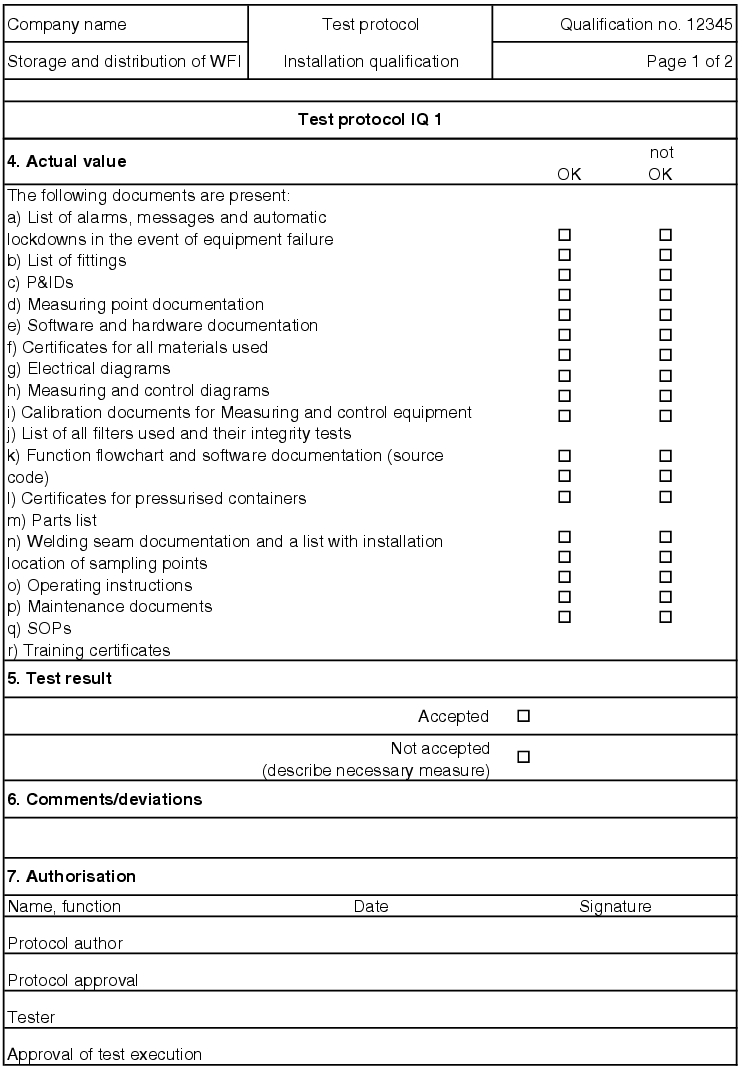
5.D.4.3 IQ test record
The execution of the test points described in the IQ test protocol is documented with a test record. The form for the IQ test record has the same type and design as that of the DQ test records. Before performance of a test, the test records are compiled by copying the test object and the acceptance criterion from the test protocol. Execution is described in detail so that the test can be repeated again identically at a later time. Before performance of a test, the IQ test records are released by the quality assurance. During execution of the test, the actual values ascertained are documented.
If the test is failed, measures are established for the individual test point. For test points for which measuring values are determined, the values must be codified in the record. If there are supplementary documents (printouts, diagrams, etc.) for the individual records, they should be saved as an appendix to the test protocol. In the end, the IQ test record decides if the test result for the respective record is accepted (see figure 5.D-15).
All open measures must be processed before the final submission. If corrective actions are necessary, a new test must be executed as part of the normal procedure for an IQ and must be recorded separately. To do this, an IQ test record with a serial number (e.g. IQ1.1, IQ1.2) can be created and saved as a second record in the documentation system.
|
|
|
5.D.5 Operational qualification (OQ)
The aim of operational qualification (OQ) is to check the equipment and function of the water supply in the context of generally established process parameters. That is, the test should not only test the actual operation, but also all permitted statuses of the facility. Temperature fluctuations, pressure fluctuations, etc. of normal operation should be documented with the test.
After successfully passing this test, operation statuses which reach the limits (worst case) should also be simulated and documented:
- Does the correct alarm sound?
- Does the facility automatically change to safety mode?
- Is the defective status correctly documented?
In addition, it is important to document that the facility is properly transferred back to normal operation after a failure or can be properly started again after a failure. In the case of an automatic water supply, it is checked to see if all valves open and close as intended, the pumps start up and generate the necessary preliminary pressure and the required requirements of the water are achieved.
Each individual process step must be checked, i.e.
- that the ion exchangers for softening work correctly and the hardness measurement can be used to prove that the softening is working.
- that the reverse osmosis membranes work correctly and the conductivity measurement can be used to prove that the desired level of separation is achieved in reverse osmosis.
- that the electrodieresis works and the conductivity measurement and TOC content measurement can prove their working method.
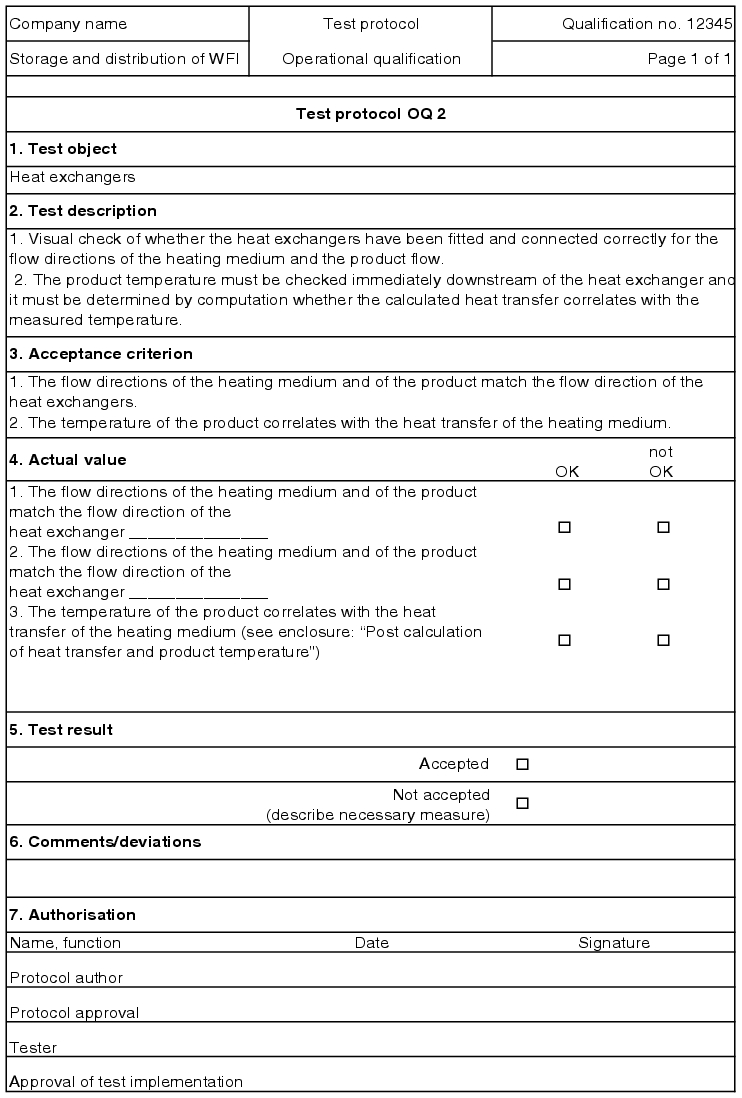
- that the heat exchangers work and the water is heated to the required temperature (temperature measurement).
- that turbulent flow prevails in the loops (with the help of ultrasound measurement).
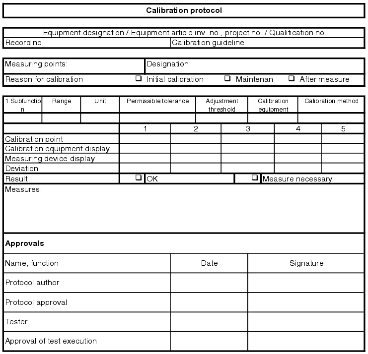
The measuring instruments required for the pharmaceutical water supply must be described in the user requirements and technical specification. This includes, in addition to the type of measurement, a definition of the required acceptance criteria such as working point or working range, e.g. temperature measurement between 100 °C and 150 °C, pressure measurement at 3.1 bar abs., calibration points, upper and lower threshold deviation, adjustment threshold and calibration interval.
This information, in particular the process tolerance and the upper and lower limit deviations, are used for technical specification of the measuring cycle, so that measuring instruments with the required level of accuracy can be procured. Using this information, the calibration specifications can be compiled and released. Before start-up of the facility or during preparation for operational qualification, an initial calibration must be carried out for all measuring instruments (see chapter 6.E.1.3 Measuring and control technology points and initial calibration).
Quality-related measuring points on water systems are usually:
- Temperature
- Pressure
- Conductivity
- TOC value (if inline measurement carried out)
|
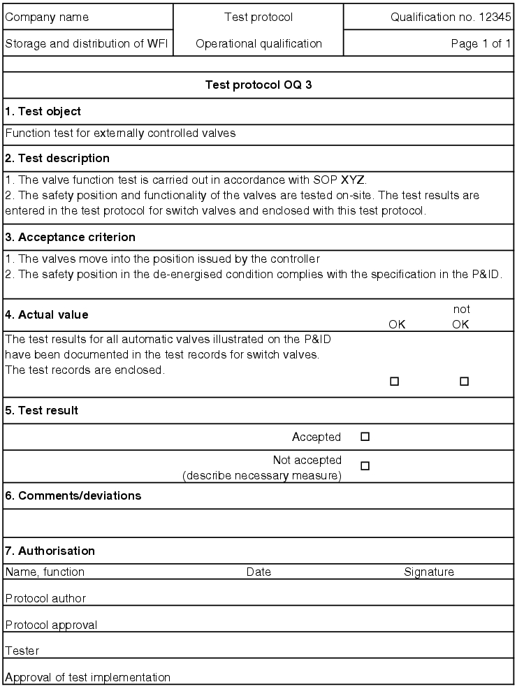
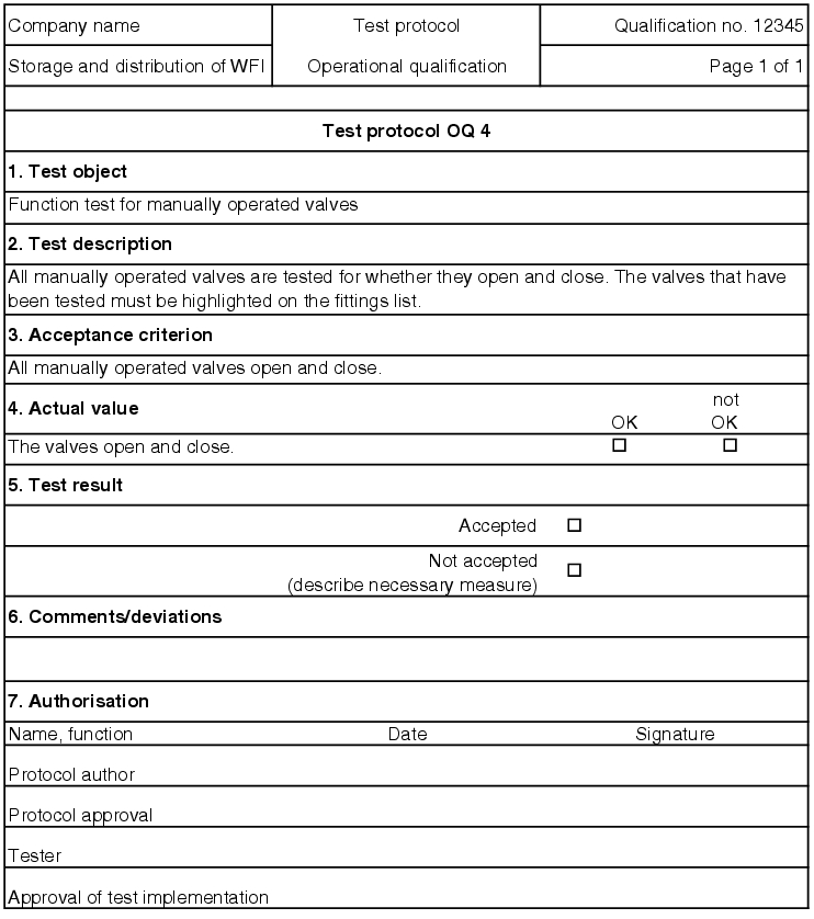
5.D.5.1 Test protocol (OQ)
The test protocol for operational qualification specifies the points that are necessary to guarantee correct operation. The test points are described that must be complied with to achieve the performance key data. In addition, the test points for the worst case scenario are listed, which must be complied with to transfer the facility to safe rest or to make it ready for operation again (see figure 5.D-17).
| OQ test protocol Pharmaceutical water supply / Inv.No. X / Qualification No. YYY |
||||
|---|---|---|---|---|
| Seq. no. |
Test item |
Test feature |
Acceptance value incl. the permissible deviations |
Record no. |
| Operational readiness of the facility |
||||
| 1 |
Pumps |
Conformity |
|
OQ 1 |
| 2 |
Function check of heat exchanger |
Conformity |
|
OQ2 |
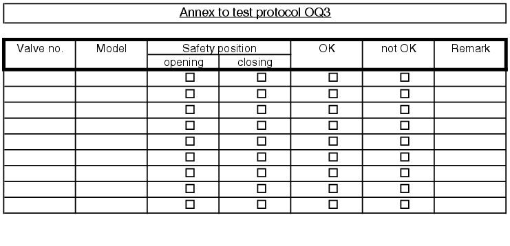
| 3 |
Function check for automatic valves |
1. Functions |
The valves adopt the actuated position. |
OQ3 |
| 2. Safety position |
The safety position in deenergised mode complies with the requirements in the installation scheme. |
|||
| 4 |
Function check for manual valves |
1. Functions |
The manual valves can be opened and closed 100%. |
OQ4 |
| etc. |
||||
| Performance test |
||||
| 6 |
Container |
1. Safety valve |
The safety valves cannot be ventilated by hand without damaging the seal. |
OQ6 |
| 2. Sterility |
It is possible to sterilise the container. |
|||
| 3. Temperature in the condensate outlet |
The temperature does not fall below 121 °C for 20 minutes. |
|||
| 4. Fill level regulation |
Fill level regulation complies with the switching points. |
|||
| 7 |
Connections to the facility |
1. Pressure fluctuation |
Feed water pressure fluctuations, max. ±3% |
OQ7 |
| 2. Pressure fluctuation |
Cooling water pressure fluctuations, max. ±10% |
|||
| 3. Pressure fluctuation |
Household steam pressure fluctuations, max. ±3% |
|||
| 4. Pressure differential |
Feed water to cooling water pressure differential at least 3 bar |
|||
| 8 |
Elutriation |
Quantity |
The elutriation quantity must be at least 16% of the feed water. |
OQ8 |
| etc. |
||||
| Safety/Worst Case |
||||
| 10 |
Safety position |
Reaction to energy failure/energy recovery |
If the energy supply fails, there is no risk to the product, people or the environment; Facility moves to a defined mode. After recovery of the energy supply, the facility only restarts after actuation. |
OQ10 |
| 11 |
Media shutdown |
Reaction to media failures |
If the supply media fails, alarms are triggered. The facility automatically changes to safety mode. Valves move to their safety statuses |
OQ11 |
| etc. |
||||
| Approvals |
||||
| Name, function |
Date |
Signature |
||
| Record approval |
||||
| Tester |
||||
| Approval of test execution |
||||
5.D.5.2 OQ test record
The execution of the test points described in the OQ test protocol is documented in an OQ record (see figure 5.D-18).

|
|
|
|
|
5.D.6 Handover to the user
After carrying out the individual qualification steps (DQ, IQ, OQ) it is advisable to summarise all qualification activities and open measures from the individual test records in a final document. Often the responsibility of the technical department in charge of qualification is handed over to the operator for the execution of performance qualification or process validation.
5.D.6.1 Handover report
For a smooth handover of the technology to the operator, a handover report is used which informs the user of the scope of testing already carried out and any ongoing measures.
The following points are codified (see figure 5.D-19)
|
|

|
- Explanation of the qualification status (qualified or not qualified)
- Name of the person responsible for the pharmaceutical water facility
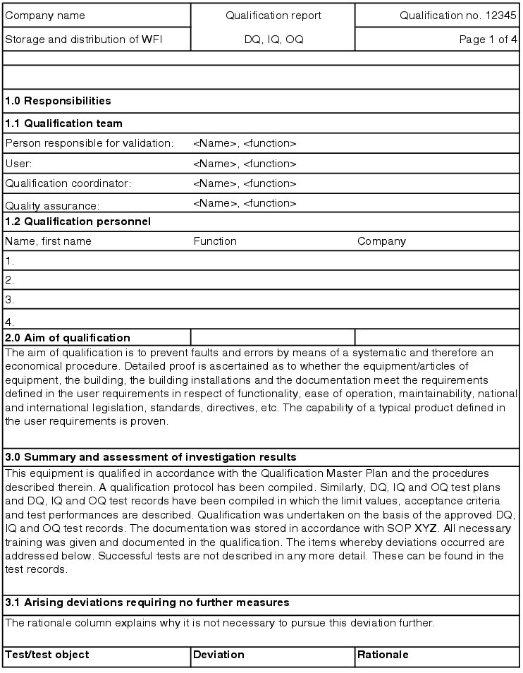
- List of all staff from the qualification team (including temporary staff)
- Summary and assessment of the test results from DQ, IQ and OQ
- Assessment of the qualification with qualification status
- Release and approval
The assessment of the test results can be split into four categories
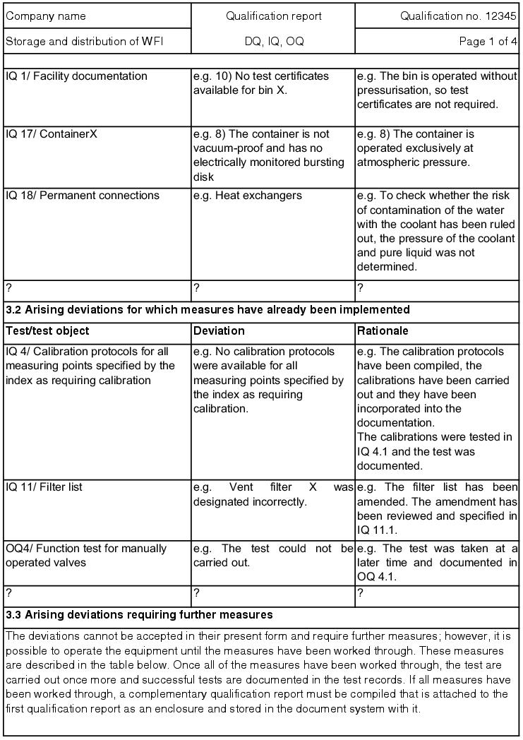
- deviations that occurred but that do not require any measures
- deviations that occurred and for which measures are currently being executed
- deviations that occurred and that still require measures and
- deviations that occurred that require the facility to be decommissioned.
So that the pharmaceutical personnel can take over or operate the water supply, the technical department or the supplier must provide training in operation and maintenance and document this training. This report, which is approved by quality assurance and by the user, represents the official handover of the water supply to the user.
Measures from the qualification report
All measures that still have to be carried out must be listed in the qualification report and are to be carried out according to the plan. The measures that have been carried out must be documented and the qualification points from DQ, IQ or OQ are to be listed for these measures in a new test record. This documents the new status of the facility. Once all measures have been carried out, a supplementary qualification report must be compiled, which is attached to the first qualification report and stored in accordance with the document system.
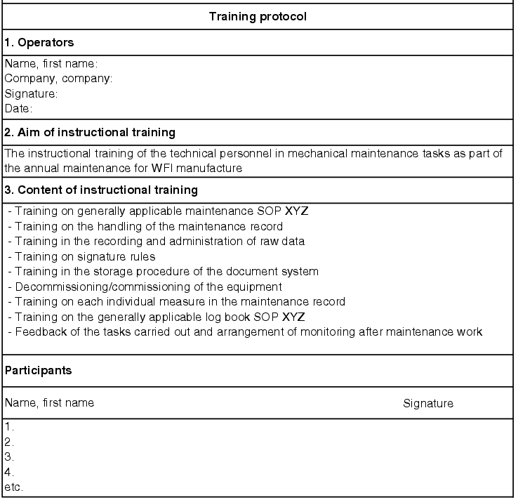
Training
The training carried out should be specifically based on the respective user. A facility operator should be trained in how to operate the water supply, a technical employee should be instructed in maintenance and repair of the facility. Training does not consist of simply pressing the operating instructions into the employees' hands, with the request to read them.
Training is both a theoretical familiarisation
- with how the facility works,
- with the SOPs and applicable regulations to be observed, and
- with the processes of handling reports on failures, entries in log books, procedures for imminent maintenance work, etc.
as well as practical training on-site.
These courses are to be documented together with the qualification (see figure 5.D-20).
|
Handover report
After approval of the qualification report by the user, a handover report is compiled, in which the user documents takeover of the facility for process validation and thus for operation (see figure 5.D-21).
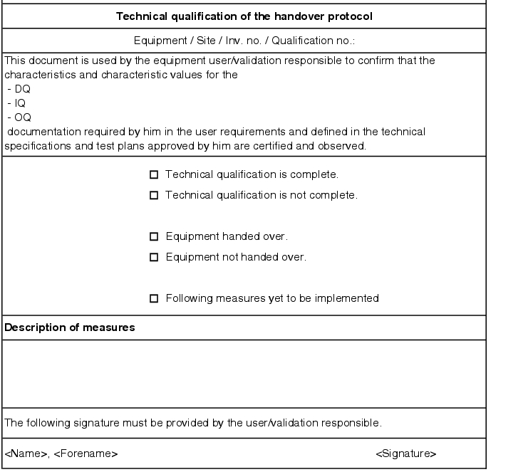
|
This action designates the step between qualification and the subsequent process validation and is used to document the transfer of responsibility for the facility from the technical department to the user.
The next phase, in which the efficiency of the facility is tested in operation, can be called Performance Qualification (PQ) or process validation (see chapter chapter 5.D.7 Process validation/performance qualification (PQ)). In order for the user of the facility to be able to execute this final validation, he must be able to access the qualification documents. In terms of the comparability of the qualification activities and the process validation, it is best if the user of the facility brings his validation protocols and records in the same form as the qualification protocols and records. With the qualification report and the handover report, the user is aware of all open measures from qualification and can judge whether or not he can carry out an initial validation for his process. However, if there are still open measures, he can have these processed immediately by the qualification team.
5.D.7 Process validation/performance qualification (PQ)
The qualification of a water supply shows that the facility produces water of the desired quality regardless of the quality of the preliminary stage of water purification and the seasonal variability. Therefore, the OQ is followed by a 12-month performance qualification (PQ), which is sometimes also referred to as process validation. It is split into three phases.
The testing parameters cover at least all quality attributes mentioned in the monographs of the pharmacopoeias (microbial count, conductivity, TOC value). They also cover:
- recording the storage temperatures
- flow rate
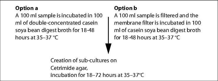
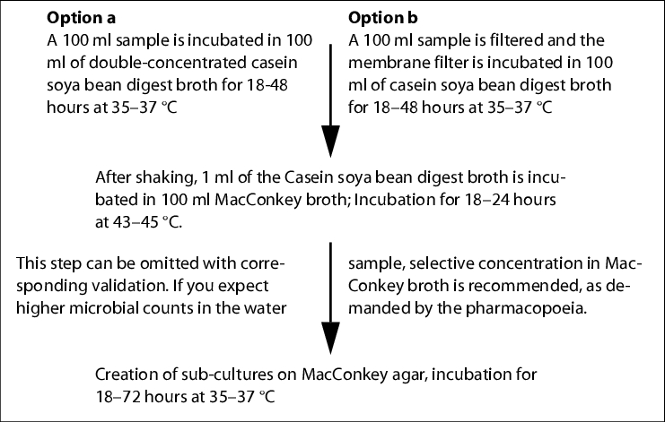
- proof of specific microorganisms
A key part is the microbiological tests, which are later incorporated into routine monitoring (with longer time intervals and selection of the sampling points to be investigated) (see chapter 5.D.7.1 Microbiological tests for pharmaceutical water).
5.D.7.1 Microbiological tests for pharmaceutical water
A main problem in the operation of water supplies is the microbiological contamination of the medium including the surfaces of purification plants, lines and tanks.
A difficulty in detecting microorganisms is that there is no easy method that records the quantity of all microorganisms present in a water sample. The methods specified in the pharmacopoeias always only allow detection of a specific range of microorganisms, as the culture media used, the selected incubation conditions, etc. only allow the growth of a specific group of microorganisms. The European pharmacopoeia prescribes the R2A agar culture medium for the total microbial count calculation in water. This agar is a medium with a small range of nutrients and is therefore good for detecting bacteria in water, especially also in biofilms. The use of culture media with small ranges of nutrient, such as R2A, often leads to higher microbial counts compared with casein soya bean digest agar in defective facilities. This means that thresholds may be exceeded more often. However, the use of a medium with a low range of nutrients also provides a good chance of detecting problems with a water treatment system in good time, and thus the chance of reacting before damage is caused to a product.
Total microbial count
To determine the total microbial count in water, the Ph. Eur. prescribes the membrane filter method (maximum pore width 0.47 mm; agar medium S (R2A agar)).
A sufficient volume is to be filtered depending on the expected colony count (WFI at least 200 ml). The incubation takes place for five days at 30-35 °C on R2A agar. Typical water bacteria, such as Ralstonia pikettii, Burkholderia cepacia and Stenotrophononas maltophilia form extremely small, transparent colonies on R2A agar (approx. 0.1 mm), which cannot be detected without a magnifying glass. Help is available in the use of a coloured membrane filter (black, grey or green).
|
|
5.D.7.2 Determination of alert and action limits
Alert limits and action limits should be set so that the action limits show a deviation from the required quality of the water. Alert limits, on the other hand, should be determined so that a deviation from the normally produced quality is shown, without violating the required quality. Action limits should reflect the respective requirements of the monographs; the alert limits should be adapted to the possibilities of the water treatment system.
When determining the alert limits, you should ensure that deviations from the normally produced values are shown, but with a certain tolerance which prevents unnecessary action.
While the action limit should be based on the pharmacopoeia, the alert limit should be determined based on the values found. It can be calculated using the formula in figure 5.D-24, for example.
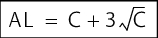
C = Average of all measurements |
For example:
If the average limit reached is 20 CFU/ml, then the alert limit is calculated using the following formula:

|
The calculated alert limit of 35 CFU/ml shows enough tolerance over the average value to compensate for variability during sampling, for example. The value is clearly different from the limit in the monograph for purified water and indicates an unusual event.
5.D.7.3 Sampling
First, you must establish which information you want to obtain from the water investigation.
Quality of the water that the facility produces
With this investigation, all influences from sampling valves, points of use, etc. should be excluded. It is advisable to use special, sterilisable sampling valves here. If these are not available, you can try to keep the influence of the point-of-use valve as low as possible through singeing and running in advance.
Quality of the water used in the production of the product
In this case, it is important for the sampling to be carried out under conditions that reflect the production conditions. If the water for production is drawn through a hose, the sampling to determine the water quality must also be drawn through a hose.
If the line is rinsed for 30 seconds before drawing the water for production, for example, this must also be taken into account during sampling to determine the quality.
The sampling tanks should at least be pure enough to be able to determine the quality of the water. So, for example, a sampling tank for determining the microbial count must be sterile, and a container for determining endotoxins must be free from endotoxins.
To determine the conductivity of a water sample, it must be ensured that no impurities in the sampling tank influence the determination of the conductivity. This can be achieved by rinsing the container with the water to be tested, for example.
5.D.8 Qualification report
Unlike the usual procedure for compiling a qualification report after completing all activities, with water systems, an intermediate report is nearly always compiled after the PQ phase II. This intermediate report is the basis for a temporary release of production with pharmaceutical water. As no pharmaceutical plant has time to wait until completion of phase III, the produced water can be released after successful execution of IQ, OQ, PQ I and PQ II. After completion of phase III, the usual final qualification report is then compiled.
After compilation of the qualification report, usually by a qualification employee, the qualification coordinator has the task of checking the report for conformance with the results of the test records and assessing the open measures mentioned in the report. In some cases, reports are compiled which show that the qualification still contains errors or gaps. These points must be described in the report under the open measures point. In this case, you could proceed as follows:
Example:
On this basis, the qualification coordinator decides if the report should be submitted to the user and thus lead to completion of qualification, or if individual or all points of the open measures still have to be completed. If these are completed immediately, the measures carried out with the test can still be processed during qualification. The qualification report is rewritten. If the qualification coordinator decides to forward the report to quality assurance, QA must also check the report and release it with its signature. Finally, the report is handed over to the user. The user checks it again and releases it by signing it or returns it to the qualification team. The qualification coordinator compiles a handover report for the user, which is signed by both. The qualification coordinator is responsible for the processing of open measures and must ensure that these measures are completed as quickly as possible. More tests must be carried out for this purpose. A supplementary qualification report must be compiled, which is to be released as described above.
In the suggested example, the overall qualification report consists of the handover report (see chapter 5.D.6.1 Handover report) and the final report after PQ phase III.
| Summary For qualification of a water supply, a separate qualification master plan should be compiled recording all components of the water generation, storage and distribution which are to be taken into account. The formal procedure complies with the principles described in chapter 6 Qualification. The main focus of the IQ is the complete documentation and correct installation in accordance with the installation scheme. After the OQ, the facility is usually handed over from the technical department to the user for PQ. For water systems, a PQ or process validation is indispensable, and is split into three phases. It is checked to see if the facility supplies a consistently good water quality given seasonal variability, i.e. over 12 months. Conductivity, temperature and flow rate in the microbiological tests play a key role. |
