5.C Distribution and storage of pharmaceutical water
|
Here you will find answers to the following questions:
|
In principle, when storing pharmaceutical water, a distinction is made between storage at room temperature and hot storage. Storage at temperatures of >70 °C generally means hot storage systems are being used. There are also systems that are operated at temperatures of <10 °C. However, these are of no significance in practice and are therefore not described here in more detail.
Storage at room temperature
In the case of storage at room temperature, there is an increased risk of biological fouling. In order to minimise this, a combined ozonisation/UV treatment is often carried out in such systems. The water is ozonised before it reaches the storage container. That is, ozone is produced from air or pure oxygen in the electrical stress field. This is fed into the water through porous gas developers, thus killing organisms or preventing microbial growth. First there is UV treatment to reduce the amount of ozone dissolved in the water and so that water without chemical additives is available at the point of use.
Hot storage (>70 °C)
Hot storage at temperatures of >70 °C is a so-called self-sanitisation system. The high temperatures prevent microbial growth and generally kill organisms. Therefore, no further measures for microbial reduction are necessary. Ozonisation/UV treatment is not recommended with hot storage, as the thermal stability of ozone at these temperatures is too low.
1 Loop
Standing water becomes fouled quicker than moving water. Therefore, a loop for purified water should be designed as a loop in which there are no areas without flow. Assuming that the pharmaceutical water, after generation, is initially collected in storage containers and is then circulated in a loop with the help of pumps, the simplified loop for purified water is as described in figure 5.C-1. .
 |
This illustration is given in more detail in the following chapters
1.1 Flow rate and turbulent flow
Depending on the speed of the medium according to its viscosity and the diameter of the tube, there will be a laminar or turbulent flow in a looped pipeline. With a laminar flow, the flow is rectified. That is, the medium does not mix with itself. In order to keep the risk of biological fouling low, a turbulent flow is required in the system. Eddies form which mix the medium with itself and also rinse the walls chaotically. This prevents the sedimentation of organisms, i.e. organisms cannot be deposited on the pipe walls, this reduces the risk of multiplication of organisms.
The flow behaviour of liquids depends on the following values:
- Flow rate v
- Viscosity of the liquid

- Density

- Pipe internal diameter (D)
The flow behaviour of different liquids in different systems is compared using the similarity calculation.
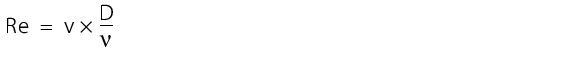
Figure 5.C-2 The result of the similarity calculation is the Reynolds number (Re). The kinematic toughness |
 is calculated from the viscosity
  / density
  .
.
The Reynolds number calculated in this way gives information on the flow behaviour in the system. Empirical investigations have shown that there is a laminar flow with Reynolds numbers of less than 2,320. With Reynolds numbers of more than 2,320 there is a turbulent flow.
Because the viscosity of water is nearly constant in a certain temperature range and the size of the system is specified, compliance with the turbulent flow is defined by the flow rate of the water.
Example: For a pipeline with an internal diameter of 40 millimetres, there is a minimum flow rate at 20 °C of 0.056 m/s, in order to achieve a turbulent flow.
1.2 Pipes
Material
In principle, one material must be established for all surfaces coming into contact with the product. The use of stainless steel 1.4404/1.4435 has proven its value here. On the one hand, the choice comes down to a high corrosion resistance, which results from the combination of components contained in stainless steel. In general, the ferrite proportion should be very low. On the other hand, this steel is one of the types accepted by the authorities. In order to satisfy the FDA, the use of AISI 316L is recommended, including 1.4404/1.4435 steels. One form of corrosion is so-called rouging. The phenomenon of rouging can occur in room temperature storage systems and in hot storage systems. The colour varies from black to dark blue through to red and red/brown. But the consistency of the rouging can also vary from a gel-type structure through to a very solid structure. It is not yet clearly determinable when and to what extent rouging can occur. In particular, the occurrence or non-occurrence cannot be forecast. It is assumed that rouging is caused by the displacement of corrosive particles in the system, with just a few components/welds of low material quality being enough to allow the phenomenon to occur. But even if the system is designed entirely with 316L, rouging is still not prevented, according to latest findings. The only countermeasure today is pickling and passivation, although it must be ensured that this does not damage the surface quality. Generally, it is sufficient to monitor the formation of rouging and take appropriate measures if the water quality deteriorates significantly.
Surface properties
In addition to the type of material, the way it is processed is also crucial. For example, the product contact surface should not exceed a certain peak-to-valley height. It is usual to work with a peak-to-valley height of Ra Ј 0.6 to 0.8 mm. In addition, the surface should be electro-polished. This procedure smoothes the peaks that occur in the material. This relatively smooth surface should prevent microbiological adherence on the surface. The high surface standard cannot be maintained everywhere, however. When using longitudinal welded pipelines, the manufacturers can comply with Ra Ј 1.6 mm on the welding seams. If this is not sufficient, drawn pipes can also be processed, although this means higher investment costs. At the latest at the time of installation in the building, however, the welds produced there will have a higher peak-to-valley height.
After installation, the entire system is pickled and passivated. Pickling removes all undesired impurities created during installation, such as greases, fingerprints, small metal parts; and the surface is marginally abraded. The subsequent passivation step then achieves a stable oxide layer through chemical reactions, which protects the stainless steel. Pickling and passivation are today already possible even for surface finishes of Ra < 0.3 mm without impairing the quality of the surface finish. Chemicals used are e.g. citric acid, nitric acid and phosphoric acid.
1.3 Requirements of welds
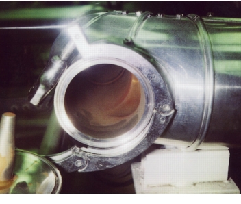
For various reasons, welds involve high risks (corrosion, particlulate matter, biological fouling). Firstly, welding is an activity carried out by people. Welding in the loop for purified water may only be carried out by trained and qualified welders who weld a sample seam every day. But even then, errors in the weld cannot be ruled out. Therefore, welding should be subject to special monitoring and documentation. Figure 5.C-3 and figure 5.C-4 show examples of requirements for welds and their documentation. In addition, it is possible to check welds using endoscopy and x-rays and also document these tests in a traceable manner. It is rare, however, for all welds to be checked with such a lot of effort. Usually, a statistical sample (e.g. 20 %) is subject to an endoscopy.
Where possible, however, automatic orbital welding is applied. In this case, the technical process data must be recorded for all welds, in order to be able to prove correct welding afterwards. TIG welds can be generated very accurately and continuously with the same quality and are therefore preferred for the installation of loops for purified water.
|
Requirements of welds |
|
|---|---|
|
1. Tungsten inert gas (TIG) welds (check visually with endoscope, for example) |
|
|
2. TIG welds |
|
|
Requirements of the welding documentation |
|---|
|
Simultaneous testing of the welds and the documentation is crucial for on-site installation, as errors could otherwise remain unnoticed. Some checks cannot be carried out in retrospect without damaging the system.
1.4 Dead end piping
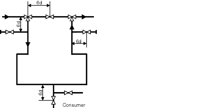
In all cases, if a branch is routed away from a streamed ring system (user, subloop, etc.) this branch must not be too long. Figure 5.C-5 illustrates the maximum distance that can exist between the main line and the shutoff device in the secondary feed line. If this distance is exceeded, the branch is called a stub or a dead leg). With a stub, it is assumed that the main flow is no longer able to continuously rinse an area after a certain length of the stub and thus protect it from cooling and/or biological fouling (areas of standing water) (see chapter 1 Loop). To calculate the maximum permissible length of stubs, the 6d rule or 3d rule is used. Here, the length from the centre of the main pipeline to the shaft of the valve in the branched line is measured. The distance determined in this way must not be longer than the diameter of the branched line multiplied by 6 or 3. If you also take into account that a minimum distance is necessary for the use of orbital welding tongs (weld between T-piece and valve), certain diameter ratios between the loop and outlet can only be released with a T-valve that is welded into the loop.
The 6d rule is generally used in systems for purified water while the 3d rule is used for WFI systems (in particular for room temperature systems).
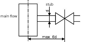 |
Figure 5.C-5 6d rule |
1.5 Use of plastics (PVDF)
An alternative material for ultra pure water systems is PVDF (Polyvinylidene fluoride high purity). This material is suitable for ultra pure water systems for the following reasons:
- No migration of material components in the water
- Very good surface finish (Ra Ј 0.2 mm)
- Permitted by FDA
- Can be sterilised by steam
- Reproducible weld procedure, very good surface properties of the weld
- Aseptic connections and fittings available
- No rouging
- Selection of measuring and control equipment available
- Compatible with other components through use of aseptic-clamp connections
Despite the advantages listed above, PVDF is not widely used in the pharmaceuticals industry. This is primary due to the following reasons:
- The material is mechanically unstable, which leads to increased assembly costs and requires particular caution when handling the material (sensitivity to bumps).
- The thermal expansion of PVDF is very large, meaning that hot systems have to be started up very slowly and the design is costly due to the necessary expansion elements.
- As the temperature rises, the strength of the material drops, meaning that the PVDF pipes in hot loops have to be laid in stainless steel shells.
- Only a few suppliers can offer and adequately process this material.
PVDF usually has no crucial advantages and generates similar costs as a design in 316L. Due to more processing operations and the positive experience with loops in 316L, many users in the pharmaceutical industry opt for a system in stainless steel.
2 Fixtures
2.1 Valves
The use of valves in a loop should be minimised, but there will always be a minimum number. Here too, the same prerequisites apply for the steel and sealing materials as for the pipelines: peak-to-valley height of Ra Ј 0.8 mm / electro-polished. In addition, for valves, it is also a requirement to ensure there are no dead spaces in the design. The properties of a dead space are difficult to describe, but in general it means any area into which the product can penetrate, but which is not necessarily rinsed out during operation. At these places, the risk of biological fouling is particularly high. So, for example, the use of ball valves for ultra pure media systems is not advisable, as there is product behind the ball which can become foul and could enter into the cycle the next time the ball valve is operated. An accepted valve is the membrane valve. Here, the entire product space is rinsed and there are no standing areas even if the valve is throttled.
2.2 Sensors
Sensors should be designed according to the same principles as valves. In particular, the selection of material is important for these elements, as there may still be some sensors that are not yet available in 316L versions. In such cases, it is often necessary to change to stainless steel of quality 1.4571. In particular, the installation instructions for the different sensors must be noted, so that medium flows against the sensors properly.
2.3 Sterile filter
Sterile filters should be entirely avoided in a pharmaceutical water system, as they present an ideal culture medium for organisms. The system should be designed so that the water quality is achieved without the use of filters. If this is not possible, an exact investigation of why the quality cannot be achieved must be carried out. This also applies for sterile filters at the points of use.
2.4 Sampling points
Sampling points should be provided in particular after containers and in the reverse flow. But it must also be possible to sample the water at the points of use. No more sampling locations should be fitted than necessary just as a precaution. On the one hand, installations are always potential sources of biological fouling and biofilm formation, and on the other hand, inspectors often ask for the analysis results or the relevance of points that are not sampled regularly.
3 Measuring technique
The same requirements are made of the measuring technique as for product-contact components in terms of materials, surfaces, drainability of residue and freedom from dead spaces.
Measurements that measure critical facility parameters, i.e. values that directly influence the product quality, are relevant for quality. So, for example, all measurements of the quality attributes listed in the monographs are relevant for quality in all cases. If a critical facility parameter cannot be measured directly, values that influence it may also be relevant for quality.
The following applies for quality-related measurements:
- Record measurement values
- Calibrate measuring points (initial and subsequent calibration)
- Define working limit, warning limit and action limit
- Define limits
- Specify the measuring range and the required accuracy (repeatability)
For compliance with the required measuring accuracy and the associated permissible tolerances, the accuracy of the entire measuring range must be observed. The errors of all components in the measuring section are added up:
Sensor error + measurement converter error + analogue card control error
In addition, a resolution is also required in the body of rules, which must not be exceeded (e.g. conductivity 0.1 mS/cm according to USP).
The following measurements are carried out routinely:
- Filling height
- Flow
- Conductivity
- Pressure measurement
- Temperature measurement
- Ozone measurement
- TOC measurement
3.1 Level measurement
An important value for the smooth operation of an ultra pure water system is the level of the containers in the system. To correctly control an ultra pure water system, certain levels are also defined that trigger different actions.
These actions can result in alert or alarm messages, but can also trigger specific reactions, such as:
- Switch on the ultra pure water generation facility to fill up the container
- Switch off the ultra pure water generation facility, if the target container level is reached
- Switch off the ring pump as dry run protection
- Close the point-of-use valves to maintain ring operation despite the low container level (risk of cavitation) until enough fresh pure water is supplied
- Overfill protection
The container level can either be measured continuously over the complete container volume or just at individual positions, at which there are corresponding sensors in the container. The second procedure is also called limit measurement.
The continuous procedures also include
- Capacitive level measurement
- Pressure differential measurement
A distinction is also made between contact and non-contact measurement.
Capacitive level measurement
Capacitive level measurement is based on the condenser principle. Measurement electrodes, product and containers form an electrical condenser. The capacity of a condenser is defined by three parameters:
- Size of the electrode surfaces
- Distance between the electrode surfaces
- Material between the electrodes (insulator)
So, the capacity of a cylinder condenser is calculated using the following equation:
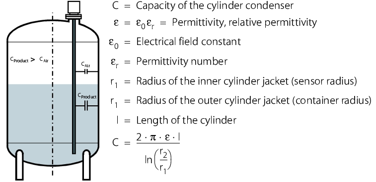 |
This equation is the basis for the function principle of capacitive level measurement. One of the electrodes is the sensor (corresponds to the inner cylinder for the cylinder condenser) and the other electrode is the container (the outer cylinder). A prerequisite for this arrangement is that the container consists of a conductive material (e.g. stainless steel) and the product is not electrically conductive.
The electrode surfaces and the spacing between the electrodes are constant, as they are formed from the sensor and the container. The air in the container and the product form the insulator. The permittivity number of air (and vacuum) is 1, and that of other materials is greater than 1, (e.g. water = 81). With increasing coverage of the electrode, the capacity of the condenser formed from the sensor and container increases.
With a non-conductive container material (e.g. PVDF), a counter-electrode (e.g. earth pipe, second probe, dual rod measuring probe, although the earth pipe is excluded here for hygiene reasons) must be used, with the second electrode also being formed by a sensor. With electrically conductive products, an insulated electrode must be used. For a continuous, capacitive level measurement, a constant permittivity number of the product is a prerequisite. This leads to problems with the level measurement of pure water containers during cleaning processes. Ultra pure water can be considered as non-conductive, with its conductivity of <1 mS/cm. If it is displaced with alkaline solutions and acids for cleaning, the conductivity becomes a multiple higher and the permittivity number changes. The result is that the level cannot be measured during the cleaning process (see figure 5.C-7).
|
Advantages |
Disadvantages |
|---|---|
|
|
Pressure differential measurement
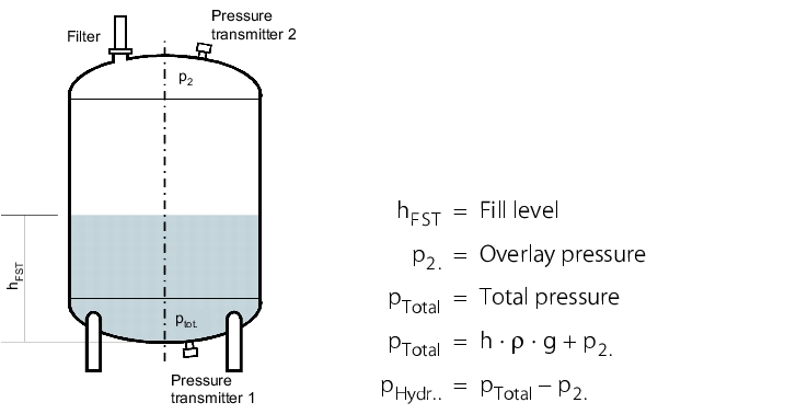
As the overlay pressure on containers overlaid with inert gas or breathed through sterile filters distorts the measurement of a hydrostatic level measurement, this pressure must be measured with a second pressure transmitter and subtracted from the total pressure measured in the bottom container section, in order to determine the correct hydrostatic pressure. This measuring procedure is referred to as pressure differential measurement, which is also used to monitor filters or measure the flow rate.
With the pressure differential measurement, there are two ways of measuring the pressure differential.
 |
- Both pressures are measured with two independent pressure transmitters. The electrical measuring signal from each pressure transmitter is forwarded to the control unit or special measuring electronics. Here, the two measuring signals are evaluated and then the pressure differential is determined.
- The pressure differential is measured with a pressure differential transmitter. This is equipped with two pressure transmitters which are connected to the pressure differential transmitter by two capillaries filled with a pressure determining fluid. From the pressure transmitter, the measured pressure is guided to the pressure differential transmitter via the pressure determining fluid. Here, the pressure differential is measured directly and an individual pressure differential signal formed (see figure 5.C-8).
The measuring ranges of both pressure transmitters should be the same and should also extend into the low pressure range. Low pressure can occur if a greater volume of water is pumped through the pump than the volume of air that can flow through the sterile filter into the container afterwards. This example should explain this:
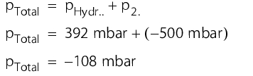
A container level of 400 mm water, with a density of 998.19 kg/m3 (at 20 °C) corresponds to a hydrostatic pressure of around 392 mbar. If a low pressure of -500 mbar is established due to a blocked filter when draining the container, the total pressure measured in the bottom part of the container is also negative (see figure 5.C-9).
|
Advantages |
Disadvantages |
|---|---|
|
|
Limit level measurement procedure
With the limit level measurement procedure, only a specific filling level of the container is measured, which is prescribed by the installation location of the measuring equipment. Possible applications for the limit level measurement procedure are, for example, overflow protection for containers, dry-run protection or monitoring of other important switch points.
- Capacitive:
The measuring principle corresponds to that of capacitive level measurement. If the medium in the container wets the sensor, the capacity changes, which is reported digitally to a control unit by a 24-V signal, for example. - Vibration limit switch:
The vibration limit switch is shaped like a tuning fork and is made to vibrate piezoelectrically. The frequency of this vibration corresponds to the resonance frequency. If the vibration limit switch is covered in medium, the resonance frequency changes, which is detected by the measuring electronics and is output as a switch signal (see figure 5.C-10).Figure 5.C-10 Advantages and disadvantages of the limit measurement procedure
Advantages
Disadvantages
- Largely independent of the medium attributes
- High operating safety, internal monitoring
- Can be installed hygienically
- Long life
- Product contact
3.2 Flow measurement
The easiest way of determining the flow is by creating a defined pressure drop with a diaphragm and using this to determine the flow rate and thus the flow volume. The flow volume, mass flow rate determination is usually used - except for quantity determination in the context of dosage processes and usage monitoring - for documentation of the flow rate in the system (preferably in the reverse flow, after the last point of use). In addition, it is also used in flow volume regulation to control the pump performance. Here, the flow volume in the reverse flow of the ring system is kept constant by increasing the delivery rate of the pump by the total of the usage volume using a frequency converter.
Mass flow measuring device (Coriolis flow measuring device)
Coriolis forces always occur when rotational movements are overlaid with translational movements (see earth's rotation, there are eddies when a container is emptied and, for example, cyclones (low pressure areas), which rotate in a different direction in the northern hemisphere than in the southern hemisphere). The size of the coriolis force occurring depends exclusively on the mass flow and thus on the flow rate.
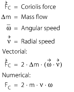
The flow rate here corresponds to the radial speed. The angular speed (rotation movement) is created by the oscillation of the meter tube with a defined frequency. The measuring tube is caused to vibrate in order to determine the mass flow. This vibration is recorded both at the inlet and outlet by electrodynamic sensors. If no mass flow moves through the tube, the inlet and outlet of the measuring tube vibrate in-phase. If a mass flow moves through the meter tube, the coriolis forces occurring cause a shift in phases between the inlet and outlet. The phase shift is evaluated by the measuring electronics and a signal for the mass flow is determined.
The mass flow measuring device also continuously determines the density of the medium based on the resonance frequency. Therefore, the mass flow can also be very accurately output as the flow volume. The temperature of the measuring tube is also recorded for temperature compensation.
A distinction is made between single tube and dual tube systems for coriolis flow measuring devices. With dual tube systems, two measuring tubes are vibrated and with single tube systems one measuring tube and a reference mass are vibrated out of phase, in order to keep the system in equilibrium (see figure 5.C-11).
|
Advantages |
Disadvantages |
|---|---|
|
|
Ultrasonic flow measuring device
Ultrasonic flow measuring devices work using the runtime difference procedure. This procedure uses two sensors which work alternately as senders and receivers. With this procedure, one ultrasound signal is sent with the flow direction and one signal is sent against the flow direction and the transfer time of the signal is measured. As ultrasonic waves move faster in the flow direction of the medium than against it, a time difference results (runtime difference). This runtime difference is directly proportional to the average flow rate. The measurement is carried out continuously, depending on the manufacturer, with a frequency of up to 1000 Hz. There are different, manufacturer-dependent designs of ultrasonic flow measuring devices:
- Sensors in the product space
- Sensors outside the product space
For designs with sensors in the product space, GMP conformity must be ensured in terms of freedom from dead spaces, freedom from gaps and the ability to drain residue.
For designs with sensors outside the product space, the sensors are applied to the outside of the pipe, meaning that no influences are exerted on the medium (see figure 5.C-12).
|
Advantages |
Disadvantages |
|---|---|
|
|
Rotameter
With rotameters, there is usually suspended matter with a geometry specifically defined for the medium and the measuring range in a conical (diameter continuously increasing upwards) measuring space. The suspended matter flows against the medium from bottom to top.
|
Advantages |
Disadvantages |
|---|---|
|
|
The flow lifts the suspended matter until the forces acting on it (weight, lifting force and flow force) are in equilibrium. Rotameters are available with cones of glass and metal (AISI316L). For devices with glass cones, the flow can be read off a scale. With the stainless steel cone design, the suspended matter position is transferred magnetically and assessed electronically (see figure 5.C-13).
3.3 Conductivity measurement
The conductivity of a liquid is its ability to transport electrical charges. As chemically pure water (H2O) is not conductive, the ions present in the water take on the role of charge transportation. Conductivity is therefore a measure for the ions present in ultra pure water.
There are two ways of finding out the conductivity of a liquid medium,
- Conductive conductivity measurement
- Inductive conductivity measurement
Inductive conductivity measurement is not possible for the measuring ranges required for ultra pure water.
With the conductive conductivity measurement, two electrodes with a known electrode spacing and known electrode surface area are inserted in the medium. An alternating voltage is created by the measurement electronics. The current flowing over the electrodes and through the medium is a measure for the conductivity. As the electrode spacing and electrode surface area are constant, the current is only dependent on the resistance of the medium. Due to the defined and known electrode spacing, the specific resistance can be determined, and the reciprocal value in turn is the conductivity.
The electrode spacing and surface ratio is expressed in the so-called cell constant (unit 1/cm). This cell constant must be known with an accuracy of ± 2%, according to the USP.
As the conductivity depends not only on the ion count in the water but also on the temperature, the medium temperature is also measured. In principle, this allows you to see that conductivity increases as the ion count rises and as the temperature rises.
The conductivity is measured absolutely (uncompensated) according to the USP. There are therefore different limits for different temperature ranges. As of Ph. Eur. 5, unlike the earlier procedure, the temperature is also measured uncompensated, although measurements with temperature compensation can also be carried out after appropriate validation.
There are two possibilities for the installation position of conductivity measurements, with different philosophies. On the one hand, installation of a conductivity measuring device in the forward flow, in order to document that the ultra pure water always complies with the monograph-related value of conductivity before it reaches the points of use. With excess conductivity, the points of use can be blocked or the loop can be stopped before the water with the excess conductivity reaches the points of use.
On the other hand, installation of the conductivity measuring device in the reverse flow of the ring system, in order to be able to detect any increase in conductivity before the non-compliant water reaches the storage container and is diluted there. The assumption is that the cause of conductivity increases is due to contamination at the points of use and that the water, if it has complied with the limits in the reverse flow, has also done so at the points of use. Of course, there is nothing to prevent the installation of conductivity measuring devices in both the forward and reverse flows.
3.4 Pressure measurement
Pressure measurements are carried out at all parts of the system at which the pressure plays an important role for the technical working of the facility. For example, pressure measurements are used in the reverse flow of ring systems to monitor the minimum flow rate or to control the pump output via a pressure regulation and frequency converter. The pressure drop at a diaphragm or valve in the reverse flow of the ring is proportional to the flow volume in the reverse flow of the ring. If water is taken from a point of use, the flow volume in the reverse flow drops and thus the pressure drops at the diaphragm or valve. The pump output is increased until the pressure drops, and thus the flow volume reaches its target value again.
In the forward flow of a ring system, pressure measurements are often used in the form of advance notifications so that the pump output (pump pressure) can be monitored.
In principle, there are two different types of pressure transmitter:
- Pressure transmitters with product-contacting sensor membranes
- Pressure transmitters for which the sensor membrane is preceded by another pressure transmitter membrane (separator membrane) and a pressure transmitter liquid
Pressure transmitters with product-contacting sensor membranes
The sensor membrane should be made of ceramic, as ceramic remains inert in the product and is also resistant to abrasive media. The material of the membrane, especially for ceramic, must be GMP conform.
The sensor membrane can be designed flush to the front and without gaps. As this is often not the case, special attention should be paid to it.
Temperature compensation usually takes place via integrated temperature recorders, with the temperature-related measuring error being significantly less than on pressure gauge systems, as the measurement on pressure transmitters with product-contacting sensor membrane cannot be influenced by the expansion of the pressure gauge liquid (see figure 5.C-14).
|
Advantages |
Disadvantages |
|---|---|
|
|
Pressure gauge
Ahead of the sensor membrane there are a pressure gauge membrane and a pressure gauge liquid, with which the pressure is transferred from the product to the sensor membrane. The pressure gauge liquid used in the pressure gauge system must be compatible with foodstuffs or compliant with 21 CFR (proof through corresponding certificate). In addition, it must be chosen depending on the required pressure and temperature ranges. Not all pressure gauge liquids are vacuum-tight (formation of gas bubbles).
The size of the pressure gauge membrane must be selected according to the measuring range. The following applies: a large membrane area for small pressure ranges and a small membrane area for large pressures.
|
Advantages |
Disadvantages |
|---|---|
|
|
For pressure gauge systems, the measuring electronics are relatively well separated from the product temperature, which means the pressure gauge systems are highly suitable for high temperature ranges. Here too there is temperature compensation via integrated temperature recorders (see figure 5.C-15).
3.5 Temperature measurement
With temperature measurement for ultra pure water systems stored at room temperature, the medium temperature of the water is monitored to ensure it does not exceed a previously defined limit (e.g. 25 °C). With hot storage systems and during heat sanitisation the temperature measurement is used to ensure that the temperature of the medium does not fall below the previously defined limit (e.g. 81 °C).
Here, the temperature measurements are usually integrated in the reverse flow. This is recommended because the water is heated on its way through the loop due to the heat from the pump, pipe friction and the effect of the ambient temperature (even if only very slightly in relation to a recirculation) and usually has the highest temperature in the reverse flow. The same applies for hot storage or heat sanitisation, except that the reverse flow is the coldest part of the ring system, as the water releases its temperature into the environment when it flows through the loop. The temperature loss can be reduced through insulation, although the temperature losses for recirculation are very low.
If there is a heat exchanger in the reverse flow of the ring system (for cooling in the case of storage at room temperature and for heating in the case of hot storage) then the measurement must be taken before the heat exchanger. A temperature measurement taken after the heat exchanger is used to regulate the heat exchanger.
The use of Pt100 temperature sensors has prevailed for temperature measurement. A Pt100 temperature sensor is a temperature-dependent, platinum measuring resistor with a resistance of 100 Ohm at 0 °C. If the temperature changes, the platinum resistance also changes along a curve. Based on this, the measuring electronics calculate a temperature signal and issue this as a unit signal; by default 4-20 mA.
With the Pt100, there are different classes of accuracy, which in turn are described in DIN EN 60751 A and B, although there are also the 1/3 DIN B and 1/10 DIN B specifications.
Heat sensors are fitted either directly in the product space or with so-called weld sleeves. These make it possible to remove the sensor during operation and separate the measuring gauge from the product space, but also increase the attenuation of the measurement section (e.g. dead time, etc.).
For very small pipe cross-sections, it is also possible to use gauge sensors. However, it must be noted that these only measure the external temperature of the pipe and not the product temperature. In addition, it must be ensured that the sensor is insulated from the ambient temperature.
3.6 Ozone measurement (online)
The ozone measurement is usually used in ultra pure water systems to ensure that there is no more ozone in the water in the forward flow of the ring system behind the UV emitter in ozonised systems (residual ozone measurement). In addition, it can also be used to prove the correct compliance with the minimum ozone concentration during sanitisation. Both are only possible with continuous online measurement, as it must be ensured that no ozone is present in the loop at any time. A measuring procedure that meets these requirements works with a sensor equipped with stainless metal electrodes. The electrodes, between which there is electrolyte, are separated from the measuring medium by a gas permeable membrane. There is a constant voltage on the electrodes. The ozone molecules can diffuse through the membrane and are reduced at the electrodes. The change in charge at the electrodes creates a current which is proportional to the partial pressure of the oxygen. This current is evaluated in a measurement converter and displayed on the screen as the ozone concentration or as a standardised signal (e.g. 4-20 mA) for further use.
There are measuring systems that can measure ozone in a concentration up to a limit of detection of 5 ppb.
The problem with ozone measuring systems is the calibration of the measuring instruments. The sensors are calibrated for ozone dissolved in water, with the calibration not being traceable and only relating to zero. Reference solutions with known and exactly specified ozone concentrations are not known, as ozone disintegrates with time.
3.7 TOC measurement (online)
The TOC (Total Organic Carbon) is a value for the organic loading of water, without indicating the type of organic loading. Today, TOC monitoring of ultra pure water systems is often done using online TOC measuring instruments. A TOC analysis in the laboratory is also usual, as the investment costs for online measurement are not insignificant and the online measurement is not explicitly prescribed. An online TOC measurement is not a continuous measurement, but an automatic, periodic measurement with the following steps per measuring cycle:
- Rinsing time
- Oxidisation and measurement
- Pause
Despite the fact that the TOC between the individual measuring cycles cannot be monitored, an online measurement is faster and better than a laboratory analysis with prior sampling. As the measurements are carried out constantly in regular intervals, you obtain a good image of the TOC of ultra pure water through online measurement. Even an emerging TOC content increase can be more easily and more quickly detected than with laboratory analysis with required sampling, as the sampling cycles for laboratory analysis are usually much lower than the measuring cycles for online measurement.
With the actual TOC measurement, all organic ingredients of the ultra pure water are oxidised to CO2 and H2O. Then the CO2 quantity is determined and, based on that, the total quantity of organic carbon is calculated.
There are three different analysis methods for determining the TOC content:
- Wet chemical procedure (laboratory analysis):
First, the inorganic carbon is blown out with nitrogen. The organic carbon is oxidised wet chemically (e.g. with sodium peroxide sulphate and UV light) to form CO2. The quantity of organic carbon is calculated from the CO2 quantity. - Thermal, catalytic procedure (laboratory analysis):
The carbon contained in the sample is oxidised at temperatures >600 °C to form CO2 and H2O. With this procedure, it is important to use a catalyst such as platinum or quartz. The quantity of carbon dioxide created is determined with a non-dispersing infrared detector (NDIR detector). The quantity of carbon dioxide calculated here is a measure of the TC content (total carbon) in the water. The quantity of inorganic carbon (IC) from the same sample is determined using acid (e.g. phosphoric acid). - Photocatalytic procedure (online procedure):
The organic carbon contained in the sample (TOC) is oxidised via UV rays. The resulting CO2 quantity is determined by measuring the increase in conductivity. To do this, the conductivity before and after oxidation is measured.
Calibration of online measurements is carried out using the so-called suitability test, which is also described as such in the Ph.Eur. This is performed with a 500 ppb standard solution of sucrose or 1.4 benzochinon. For calibration, the TOC measuring instrument manufacturers also supply other calibration solutions with lower concentrations than 500 ppb, as the measuring instruments not only have to be calibrated to their upper measuring range limits, but also the lower limits.
4 Formation of biofilms
A big problem with water supplies is the colonisation of the surfaces with microorganisms (biofouling). In water purification, microorganisms are essentially brought in through raw water, air, contaminated facility components or materials and leaks. Only a very small number of the organisms from these potential contamination sources actually reaches the pharmaceutical water. The majority of the organisms colonise the water purification system as a biofilm. The prerequisites for a biofilm are the presence of microorganisms, surfaces and nutrients. In the biofilm, which consists of microorganisms and a layer of slime (10-90% of the biofilm), all kinds of abiotic particles from the water can be stored. Not only living microorganisms, but also dead ones can trigger the formation of a biofilm through passive adhesion.
There are three phases in the formation of a biofilm:
- Induction phase
The duration of this phase cannot be predicted. It appears to depend largely on the material, the cell count and the surface (roughness) of the material. During the induction phase, no significant changes are noticed in the process parameters. - Logarithmic growth phase
Here, the temperature and range of nutrients are the main factors. The influence of the cell counts caused by the division of cells in the biofilm, is greater than the influence of the cells that are adsorbed on the biofilm surface from the free water. The growth rate decides how quickly the next phase is reached. - Plateau phase
In this phase, growth and dissolution are balanced. With thick biofilms, it is possible for entire pieces of the biofilm to dissolve. Depending on the thickness of the biofilm, an oxygen gradient may occur within the biofilm which also enables growth of anaerobic organisms in an aerobic system.
An indication of biofilm formation can be the occurrence of microbiological overruns, for which there is no obvious cause. Retests are often within the permissible limits and show no other special features. Likewise, the occurrence of undesired germ species, which did not occur during validation, for example, can indicate the presence of a biofilm. The strong presence of a biofilm can often be clearly proven on gasket rings.
Once a biofilm has appeared, it is virtually impossible to eliminate it again. The biofilm protects the organisms against the influence of biocides. It is reported that microorganisms in biofilms are 1,000-1,500 times more resistant to biocides than organisms that are not in biofilms. Disinfectant kills the organisms, but does not release them from the surface. The dead organisms are then used as a source of nutrients for the survivors.
|
Cleaning methods for biofilm reduction |
||
|---|---|---|
|
Chlorine |
50-100 mg/l |
2-3 hours |
|
QAVs |
300-1000 mg/l |
2-3 hours |
|
Peracetic acid |
0.02-0.05% v/v |
2-3 hours |
|
H2O2 |
50-100 mg/l |
2-3 hours |
|
Iodine |
50-100 mg/l |
2-3 hours |
Even mechanical cleaning (scraping) cannot remove the entire biofilm, and the remaining residue of the biofilm acts as a starting point for the new growth of the biofilm, this is the only way of keeping a biofilm under control.
Due to the biofilm problem, you should try to prolong the induction phase of a biofilm. This can be achieved through hot storage of the water or through regular disinfection (e.g. with ozone, rinsing with hot water) of the facility (figure 5.C-16).
Organisms that are frequently isolated from biofilms:
- Pseudomonas aeruginosa, Ps.fluorescens, Ps. saccharophila, Ps. luteola
- Burgholderia cepacia, Stenotrophomonas maltophilia
- Legionella, Aeromonas, Acinetobacter, Mycobacterium, Flavobacterium, Klebsiella, Escherichia
- Bacillus sp., Clostridium sp.
5 Rouging
Rouging is a phenomenon that often occurs in water supplies made of austenitic CrNi steel. The phenomenon has not been clearly explained to date. Notes on the mechanism of rouging formation and the influencing parameters have been described several times in the past. At present, continuing scientific work is planned for adequate explanation of this phenomenon. It will therefore be some time before all facts are known consistently and before measures are scientifically recognised for safe prevention of rouging and used in technology.
In the GMP bodies of rules, the subject of rouging is not addressed. Only the ISPE Baseline Water and Steam contains marginally helpful information. It is recommended to reduce the temperature and protect the system through passivation.
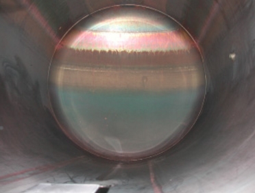
5.1 What is rouging?
Rouging mainly occurs as a red-brown particulate precipitate in hot ultra pure water systems (figure 5.C-17). In this form, the rouge coating can be wiped off. The flowing medium transports the rouge particles in the entire pipeline right into the dead spaces, pumps and containers and stores it there. In pure steam systems, rouging also occurs as a fixed adherent coating. This coating is of a black-purple colour (figure 5.C-18).
|
 |
|
Figure 5.C-17 Rouging in WFI |
Figure 5.C-18 Rouging in pure steam generator |
It is often said that rouging only occurs in pipes and containers for desalted water, which requires higher temperatures, but this is to be verified. Even cold water systems show similar discolouration and coatings. However, a tendency can be recognised, that the higher the temperature in the system, the greater and more probable the risk of rouging.
The high water temperature always leads to the occurrence of ions through the self-dissociation of the water. These ions represent concentrated acids or bases and are very reactive: 
The occurrence of rouging can be observed with all known types of stainless steel which are traditionally used in pharmaceutical facilities, such as 1.4435, 1.4404 and 1.4571. The frequently discussed content of deltaferrite and its limitation according to the Basel Standard BN2 (sheet less than 0.2% deltaferrite and pipes less than 0.5% deltaferrite) has not lead to a reduction in rouging according to information and findings to date.
5.2 Impact on the water quality
The coloured precipitates are, chemically speaking, the different forms of iron oxide and iron hydroxide. However, Cr and Ni-oxides or hydroxides are also found. Due to the very low solubility in water of ions made of these compounds, no iron ions which justify an objection about the water can be detected. No change in the specific conductivity is observed either. In respect of the monographs in the pharmacopoeias, water from pipes with rouging cannot be chemically rejected. Even the limit for the heavy metal parameter is not reached or even exceeded.
The carrying in and out of particles is a particular problem in affected systems. There is a likely risk that particles - usual rouge particle size is from 0.01 to 10 mm - will be transported into the product. The facility must therefore be very closely monitored and, if rouging is detected, a suitable measure must be taken. With an open facility, notes about rouging are often found on the seals (Teflon), as the transported particles tend to gather at these seals. As the particles are usually very small, they are not detected as visible particles. Visible particles are usually larger than 50 mm.
5.3 Handling rouging
In principle, premises and equipment must be designed, implemented and maintained in accordance with the EU-GMP-Guideline, so that they are suitable for the intended operations. But what happens if it is clearly known that a material could possibly release particles into the water causing contamination? The problem of rouging should be taken into account during validation of a facility or during requalification and ways of dealing with it should be considered and documented.
In practice, however, the subject of rouging is not taken into consideration during risk analysis or facility qualification. A reason for this is the fact that the problem should not appear in the documentation, if possible, even though actively dealing with the problem corresponds to good GMP compliance. The fact is that rouging cannot currently be prevented when stainless steel is used. A suitable alternative would be a material such as PVDF, but this currently finds little acceptance in the pharmaceutical industry and in particular involves problems with hot water systems (thermal expansion) (see chapter 1.5 Use of plastics (PVDF)).
As, in practice, the occurrence of rouging should be anticipated in particular in hot pharmaceutical water systems, all facility documentation should deal with the subject of rouging. If possible, the subject should be discussed even at the planning stage and possible measures should be documented during the risk analysis and taken into account during maintenance and cleaning. Also, the use of electro-polished surfaces can be an effective means of protection for a new facility. With existing facilities, close monitoring with corresponding documentation is recommended. Through regular inspection, possibly with specifically fitted devices, timely detection is possible. If necessary, the starting status can be restored through cleaning (derouging) and re-passivation of the system.
5.4 How can you detect rouging?
There is a device that can be used for measuring the level of rouging. The measuring principle of this inline device is based on the reflection measurement of surface shine levels and their intensity. With a glossy surface the reflection is much better than on a surface which has already been discoloured by iron oxide and coated with rouging particles. The different, saved, possible statuses of a rouge surface are compared with the measured values and displayed optically (figure 5.C-19).
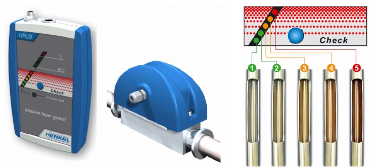 |
The starting basis is a non-discoloured metal or electro-polished surface (1). The initial stages of rouge formation are shown by a reduction in the passive layer (2) and in later stages leads to initial surface discolouration - rouge begins (3). As rouging increases, the warning level rises (4). Cleaning (derouging) and re-passivation of the facility must be carried out at the latest at the red warning level (5).
With this very simple measurement, monitoring of rouging is possible at any time. The facility operator also shows the authorities that he is dealing proactively with monitoring and rouging.
Another method of rouge monitoring is to check the particle counts. This is, for example, the state-of-the-art in the electronics industry and is a fixed part of quality control there. Without much technical effort, such checks could also be possible in pharmaceutical water systems. These checks are only rarely encountered, however.
5.5 Measures against rouging
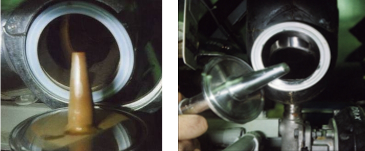
If a rouge coating is ascertained in a pharmaceutical facility, a suitable measure must be implemented. This can, for example, be chemical cleaning of the rouged surfaces through cycle rinsing (figure 5.C-20). The rouge coating is chemically dissolved and complexed, so that it can be rinsed from the system in a controlled manner. This is done using cleansing agents that chemically dissolve and remove the rouge coating and which do not permanently damage the stainless steel surface. In order to achieve the original passive state of the stainless steel surface again, the cleaned/de-rouged surface is re-passivated wet chemically.
It is recommended to have any derouging operations carried out by a specialist company with the necessary know-how in dealing with chemicals and rinsing water as well as the necessary safety technology and, on the other hand, has many years of experience with chemical surface treatment of stainless steel.
 |
It should also be mentioned that successful cleaning measures also require pharma-compliant documentation of the operations, in addition to residue-free cleaning of the rouge coating from the stainless steel surface.
|
Summary If stainless steel is used as the material, the occurrence of rouging cannot be ruled out. The water still meets the chemical specifications, but there may be undesirable particles. Therefore, water supplies and lines should be visually inspected regularly for rouging. The rouging problem should be recorded in the GMP-conform planning (risk analysis) and operation of a facility (maintenance). A rouging layer can be removed by chemical cleaning and subsequent passivation. |
6 Buffering of ultra pure water
Storage container
Storage containers are used to balance production and consumption fluctuations. In general, the aim is to continuously produce a production quantity of a water treatment system distributed over the entire day. Consumption, on the other hand, is often subject to significant variability. If the quantity produced and the quantity consumed are distributed constantly over the day, then there is no need for a storage container.
The design of a storage container is subject to the same rules as the rest of the loop.
- Use of 316L
- Surface finish < 0.6-0.8 mm, possibly electro-polished
- Material proof via material certificate
- Documented welds
- Pickling and passivation
- Use of adequate sensors and instruments
In addition, it must be ensured that the upper torispherical head of the container and the dry surfaces are rinsed with water. This is achieved with a so-called spray bowl, but this must also be designed that it too is moistened.
It is also important for the container to be ventilated and deaerated with a sterile filter. This sterile filter should be heated for hot systems so that no condensate can form in the filter. If condensate blocks the filter, the container could explode or implode. The filter should be fitted so that it is self-draining if condensate forms in the filter.
Buffer concept
Many systems, in particular small and medium-sized systems, can manage with a single loop with storage containers. Dimensioning of the storage container should take into account how quickly any defects in the pharmaceutical water purification can be eliminated (e.g. pump replacement). Such times can be bridged with correct dimensioning. For complex and spacious systems, it is recommended to establish sub-structures in the system, e.g. with intermediate storage containers. The advantages and disadvantages of such a sub-structure are listed in figure 5.C-21.
|
Advantages and disadvantages of the use of intermediate storage containers |
|---|
|
Advantages
|
|
Disadvantages
|
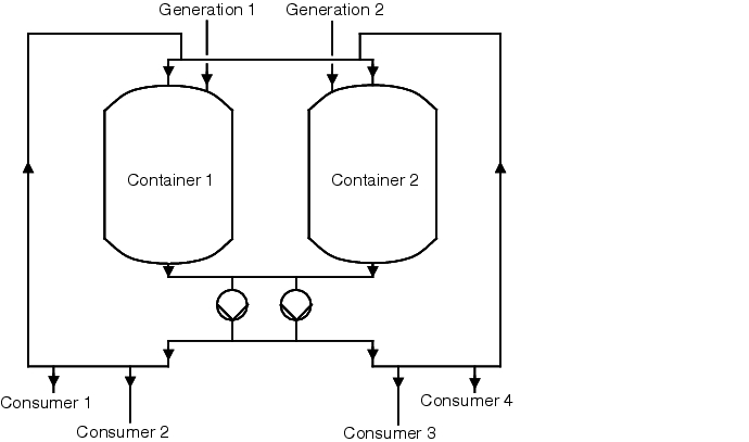
Figure 5.C-22 should clarify how buffer containers are supplied by main containers, for example.
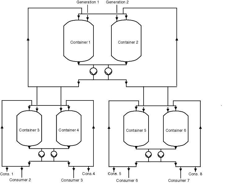 |
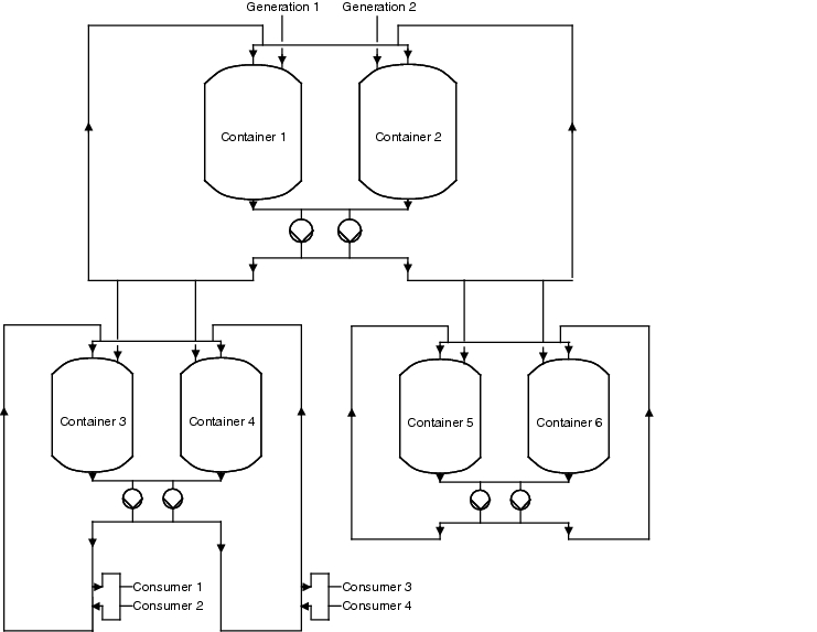
7 Loop with subloops
Following the explanation of how loops can be connected with each other, we will now explain how a subloop is connected. It should be noted that the user is not provided in the loop, but in the subloops (see figure 5.C-23). If a user has to be connected, separated or maintained, only the associated subloop must be decommissioned, while the rest of the system can continue to work (see chapter 7.2 Valve groupings).
 |
7.1 Cleanability of the loop for purified water
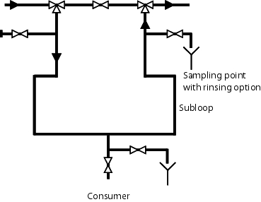
As seen in figure 5.C-24, there should be a connection at every loop or subloop at the start and end of a loop. When cleaning the system, for example with pure steam, the steam can be connected to the start of the loop. Another prerequisite is condensate deflectors at the deepest part of the system and temperature recorders in the condensate deflectors for monitoring the success of sanitisation (see also chapter 5.E.1.1 Sanitisation).
After steaming, the system should be rinsed with the pure medium. As shown in figure 5.C-26, the sampling location is connected or opened in the reverse flow. Then the forward flow is opened and the medium is rejected through the subloop and the sampling point. At the sampling location, the sample can be taken after a defined rinse cycle. After the result has been approved, the valve to the loop can be opened and the sampling valve closed.
7.2 Valve groupings
In order to comply with the 6d or 3d rule (see chapter 1.4 Dead end piping), it is necessary to keep the valves as close together as possible in a group. When connecting a subloop to a loop, this can appear as shown in figure 5.C-24.
 |
 |
 |
|
Figure 5.C-25 Subloop during maintenance and repair |
Figure 5.C-26 Start-up of a subloop (rinse) |
In order to realise this connection, blocks of valves can be used as well as individual valves that are grouped together.
|
Summary The design of the distribution and storage is a significant part of a GMP-conform pharmaceutical water system. A distinction is made between hot storage and storage at room temperature. The key influence on the water quality is exerted by the materials used and the surfaces of the pipelines, but also all fitted parts, such as sensors and valves. The formation of biofilm can be prevented through hot storage, disinfection and cleaning. Depending on the number and structure of the points of use, the design of the loop for purified water can range from simple ring structures to complex structures with several storage containers, loops and subloops. |
