Generation of pharmaceutical water
|
Here you will find answers to the following questions: |
In the pharmaceutical industry, water systems represent one of the core pieces of production. In particular when planning facilities, the importance of the design of the water systems soon becomes clear. It is not unusual for large parts of a product to consist of pure water. For parenteral products, this share is close to 100%. If you have the task of planning and installing new systems, you must take note of the regulations (FDA: Guide to Inspections of High Purity Water Systems) and thus guarantee a reproducible quality of the pharmaceutical water. In addition to these requirements, high availability of the systems must of course also be guaranteed.
In light of this, the principles that are fundamental for engineering, qualification (see chapter 5.D Qualification of water supplies), later use and in-situ inspection must be addressed here.
Depending on the application of the pharmaceutical water and the necessary availability in the company, a pharmaceutical user should consider whether or not the facilities should be designed redundantly (i.e. in multiple implementation). This may increase the investment costs, but they can be recovered again quickly through business management. All facilities presented below are subject to a certain level of maintenance that can be planned. That is, they must be shut down and maintained in specific intervals. Even if the scope of maintenance can take several days, it can be carried out in times in which no production is to take place, depending on the order of magnitude of the system. Unfortunately, however, these systems have only limited reliability and failures in the system will rule out an availability of 100%. Therefore, when calculating availability, the losses that might occur during one day of operating downtime must be taken into account. Last but not least, system downtimes are also always a quality risk. The quality must not be neglected under the pressure of production constraints. If high availability of the facilities is required, a redundant design is absolutely recommended. This can vary the percentage rate for which one facility can cover the total demand of a medium in the event of failure of the other facility from 50-100% in favour of the investment costs.
1 Purified water (PW)
In order to produce the chemical and microbiological quality described in chapter 5.A Water types and at the same time comply with the regulations, facility components are required which, in a certain composition, can be considered as a facility for generating purified water. The raw water must be pretreated before actual purification. Thus, a facility for generating purified water consists of several components which are described below.
1.1 Airbreak
In order to protect the public water supply from contamination, it is necessary to install a so-called airbreak between the first processing step in the generation of purified water and the feed of potable water. This is in order to rule out reverse contamination in the public water supply. The only requirement for this is the physical separation of the two systems. The systems can be separated in various ways. It is possible to install a supply separation container or use a supply or nonreturn valve.
1.2 Softener
The potable water is first coarsely filtered, then the so-called scale (calcium, magnesium, sulphate, carbonate) is removed in a first stage. Softened water is the prerequisite for the next stage in the manufacturing of purified water, as otherwise there could be scaling of magnesium and calcium sulphates on the membranes of the reverse osmosis units. A choice procedure would be softening using ion exchange technology. A sodium exchanger can be used for this purpose. The magnesium and calcium ions present in the water are deposited in the resin in exchange for sodium ions. Figure 5.B-1 illustrates this operation.
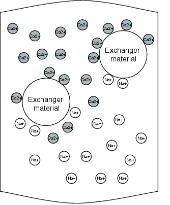 |
Figure 5.B-1 Schematic diagram of softening through ion exchange |
 |
 |
|
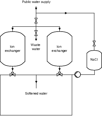
Figure 5.B-2 Operation of the ion exchanger |
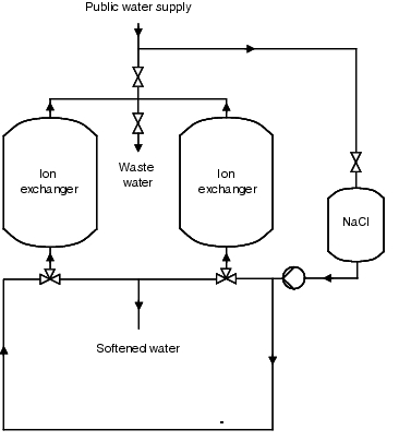
Figure 5.B-3 Regeneration of the ion exchanger |
As the resins have to be regenerated periodically, such facilities are operated discontinuously. Once exhausted, the ion exchanger is rinsed with a saline solution. In order to guarantee a continuous softened water supply for the subsequent processes, two ion exchangers are often operated in reciprocating mode. The softened water generated is monitored by means of a hardness measurement. In order to counteract a biological fouling of the resins, the facility should be dimensioned so that the ion exchangers can be regenerated every 24 to 36 hours. Figure 5.B-2 and figure 5.B-3 show the operating and regeneration phases of a facility. The medium flow and the valve settings should also be illustrated.
1.3 Removal of chlorine
When designing a facility for generating purified water, the individual circumstances of the generation location must also always be taken into account. In addition to dimensioning the facility in line with the water volumes to be provided, it is important to pay attention to the quality of the raw water used. Only potable water can be used to generate pharmaceutical water. The composition can vary greatly, however. It is possible, therefore, for the potable water used to have been chlorinated. As the raw water must be free from oxidation media, however, dechlorination through activate charcoal filters or dosage of sodium hydrosulphite (Na2HSO3) is used.
Activated charcoal filter
The use of an activated charcoal filter for dechlorination of the potable water is a simple and very effective method that should only be used for purification of potable water. When manufacturing ultra pure water the use of activated charcoal is questionable. Due to the large inner surface of the activated charcoal (500-1 600 m2/g) and the large supply of nutrients for microorganisms, the risk of increased microbiological fouling and the formation of a biofilm (see chapter 5.C.4 Formation of biofilms) is very high. Impregnation of the activated charcoal with elementary silver reduces the microbial load of the activated charcoal. Due to the oligodynamic effect of silver, it kills microorganisms in the water.
Dosage of sodium hydrosulphite
For dechlorination with sodium hydrosulphite, this is added to the raw water. Sodium hydrosulphite combines with the chlorine, which is then separated through reverse osmosis. The added quantity must be adjusted.
Removal of carbon dioxide (CO2)
Carbon dioxide represents a problem when generating purified water via reverse osmosis, as it is not retained by the membrane of the reverse osmosis and thus leads to increased conductivity. In practice, two methods are used to remove carbon dioxide.
- Dosage of sodium hydroxide solution
By adding small quantities of sodium hydroxide solution (pH value increase), carbon dioxide is converted into carbonate, which is retained by reverse osmosis. - Membrane degassing
The gases dissolved in the water are diffused through a membrane through the creation of a particle pressure difference and are rinsed from the membrane using air.
1.4 Reverse osmosis
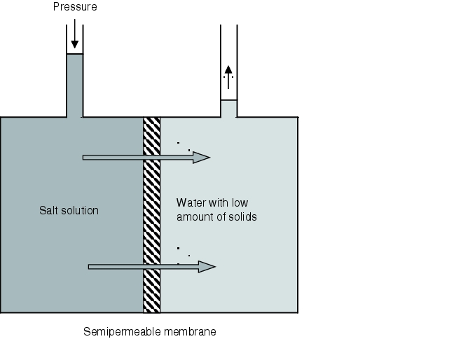
Deionisation and removal of microorganisms can be carried out in the reverse osmosis unit. Reverse osmosis is a physical operation which takes place on membranes. It reverses the process of osmosis known from the animal and plant world. A semipermeable membrane retains cations, anions, colloidal systems and bacteria. The membrane lets through water that is almost pure. With reverse osmosis, more than 98% of salts are retained, 90% of organic compounds - as well as bacteria and organisms, where 100% retention is not possible.
In order to reverse the process of osmosis, pressure higher than the osmotic pressure must be applied to the concentrate stream in order to push water with a low amount of solids through the membrane. This process is shown schematically in figure 5.B-4.
 |
The reverse osmosis units therefore work with a high operating pressure of more than 15 bar (positive pressure). Reverse osmosis units are today designed so that feed water flows over the membranes tangentially. The flow of water splits into two parts. On the one hand the concentrate, and on the other hand the permeate. The concentrate with the high amount of solids is rejected and fed into the wastewater system down to a residual share of around 10% which is fed again before reverse osmosis.
As the purified, low salinity permeate does not yet meet the required level of quality, it flows to the inlet side of the second stage of reverse osmosis. This basically works in the same way as the first stage. However, the quality of the concentrate is better than that of the pretreated raw water. Therefore, it is all fed to the first stage. The permeate of the second stage has the quality of purified water and is fed into the loop for purified water.
Reverse osmosis units essentially consist of:
- high pressure pump
- membranes (filter/permeator)
- pressure valve
- safety valves
- measurement and control devices
The core of the reverse osmosis unit is the membranes. There are hollow fibre membranes (operating pressure approx. 28 bar), spiral wound membranes (operating pressure approx. 40 bar) and low pressure membranes (operating pressure approx. 15-18 bar). Low pressure membranes are used for the desalination of water with a lower total salt content than max. 2000 ppm. They are designed as spiral wound membranes. The performance of a reverse osmosis unit depends on how many membranes are operated in parallel.
For protection against heavy mechanical loading, a fine filter is fitted 5 mm upstream of these membranes.
The salt rejection of reverse osmosis is essentially influenced by the yield. The yield is the ratio between the permeate volume flow and the supply water volume flow. The salt passage increases as the yield rises. Therefore, an optimum between permeate quality and permeate yield must be determined for each application case.
With a multi-staged reverse osmosis unit with upstream ion exchanger, a permeate with a TOC content of less than 100 ppm and a conductivity of around 0.5 to 0.6 mS/cm can be achieved.
For consistently good water quality with a reverse osmosis unit, the following points must be noted:
- Measurement of the colloidal index of the feed water and removal of the total alkalinity as well as sulphates and carbonates
- The feed water should be pre-filtered and adjusted to a pH value that does not damage the membrane.
- The feed water and the product water are to be monitored in terms of microbiological quality. The system should then be disinfected if the microbiological limits are exceeded.
- All systems should be mechanically cleaned before disinfection. Corresponding tests must then guarantee that the disinfection chemicals have been completely removed from the system.
- The use of filters or ion exchangers after the reverse osmosis modules should be avoided due to the associated risk of fouling.
- The reverse osmosis system should be designed so that there are no closures, dead legs and pipes in which standing water can form.
1.5 Electrodeionisation (EDI, CDI)
Electrodeionisation (CDI = Continuous Deionisation; EDI = Electrodeionisation) is a desalination process based on electrodialysis and mixed bed technology. EDI works by coupling the behaviour of ions in the electrical field with membrane technology. The anions wander towards the anode and pass an ion-selective membrane which transports the anions but not the cations or electrically charged particles. The cations are transported towards the cathode in the same manner. Electrodeionisation is illustrated schematically in figure 5.B-5.
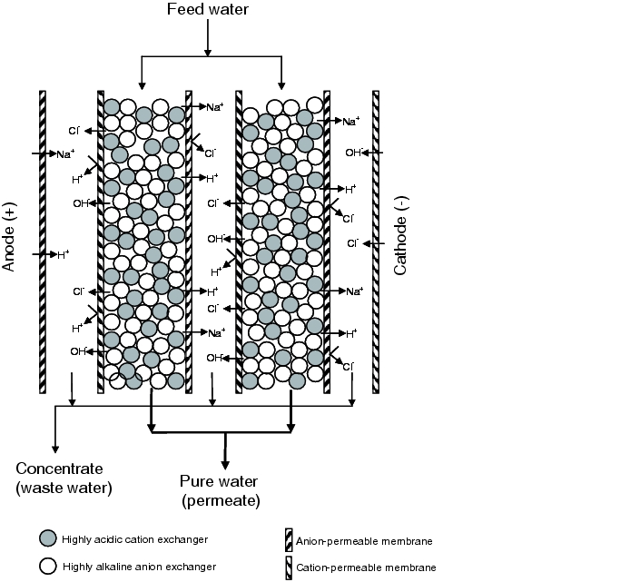 |
Through the alternate overlapping of anion or cation permeable ion exchanger membranes, parallel water flows are formed which feed water with alternating high ion concentration (concentrate) and low ion concentration (diluate) through the creation of an electric field. By bundling these channels, a diluate and a concentrate reject stream are lead away. The concentrate is fed into the reverse osmosis as feed water. The diluate stream meets the requirements of purified water and is fed into the water loop.
Water with a low ion concentration has a very high electrical resistance, which leads to diminished ion transport. For economical generation of pure water, a mixed bed ion exchanger resin has therefore been filled in the product stream. This counteracts the electrical resistance and keeps the ion migration process in order. The creation of an increased electrical current means that not only the ions are transported in the electrical field. It also means that water is split into hydrogen and hydroxide ions. These permanently regenerate the ion exchanger resin.
The operations inside the EDI module can be imagined as follows: First, the mixed bed ion exchanger resin is charged with ions. These then migrate towards the cathode or anode, as described above. Desalination at the start of the electrodeionisation module causes the conductivity in the product stream to fall. In the lower part of the electrodeionisation, the water is dissociated due to the reduced conductivity. The pH value changes locally, which means weaker electrolytes, such as carbon dioxide are also separated. In the lower part, the ion exchanger resin is regenerated through the increased level of dissociation of the water. The regeneration zone for the ion exchanger resin moves further towards the end of the product stream the greater the loading of the feed water with ions. That is, the lower the conductivity of the feed water, the lower the conductivity of the generated purified water.
Water qualities with conductivity of less than 0.1 mS/cm cannot be achieved with an EDI/CDI module alone. In order to achieve these conductivities, the feed water must be pretreated. If, for example, an upstream reverse osmosis produces a permeate of <50 mS/cm, which feeds the EDI/CDI module, conductivities of 0.055 mS/cm are possible (theoretical minimum conductivity).
|
Advantages of EDI |
|---|
|
For a water feed with a TOC content (Total Organic Carbon) of less than 0.1 ppm, a TOC content of less than 5 ppb can be achieved during continuous processing. This very good TOC removal with EDI/CDI technology is due to two mechanisms. On the one hand, after hydrolysis, the ions are transported through the membrane and removed. On the other hand, other molecules are polarised, superficially electrically charged and then pass the membrane.
A positive side effect of the EDI/CDI process is that electrochemical membrane processes, and thus also the EDI/CDI, are antibacterial due to the electric field. The advantages are summarised in figure 5.B-6.
1.6 Ultra filtration
Ultra filtration (UF) is a separation technology for separating particles with a size of 0.001 to 0.1 mm. For ultra pure water production UF hollow fibre membranes are usually used. As a UF membrane cannot retain salts, the conductivity of the permeate remains nearly the same as that of the feed water. The operational costs of a UF facility are lower than those of a reverse osmosis unit due to the lower operating pressure (lower energy consumption). Another advantage over reverse osmosis is the temperature tolerance of the membranes. The working temperature can reach 80 °C and steam sterilisation is possible in modern UF membranes up to 128 °C.
Ultra filtration is often seen as an alternative to microfiltration plants. Often, older microfiltration plants which are used as pretreatment sections for reverse osmosis are replaced by ultra filtration modules. This means a higher flux and a longer life can be achieved with the reverse osmosis modules. The problem of biofilm formation (see chapter 5.C.4 Formation of biofilms) can also be displaced from the reverse osmosis membranes to the UF membranes. This is advantageous, as UF membranes are significantly easier to clean.
1.7 Ion exchanger
In the ion exchanger (separate bed and mixed bed system) ions are removed from the water. Ion exchangers are filled with special resins which are usually produced from synthetic polymers as balls (particle size 0.3-1.5 mm) (see chapter 1.2 Softener). The particular ion exchanger resin must be selected according to the desired exchange or absorption process. Ion exchanger operations used today should fulfil the following points:
- wide utilisation of the exchange capacity
- ultra high quality of produced water
- consistent quality of produced pure water
- minimum regeneration material excesses
- low pressure losses in the ion exchanger
- maximum mechanical and chemical stability of the resin
- high availability
- compact, cost-effective construction
- simple design
- simple operation
- simple process automation
- possibility of external regeneration (backwash) of the resin without interrupting production
This procedure has become less important than EDI, as ion exchangers always have a high potential risk of biological fouling.
1.8 Purification plants
The particular combination of procedures usually depends on the feed water quality. Usually, the analysis results from the potable water supplier can be used for initial planning regarding which combinations will give the desired result. There are feed water qualities for which the combination of reverse osmosis with an EDI is sufficient for the generation of purified water. For other feed water qualities, softening, reverse osmosis, CO2-degassing and EDI must be combined to achieve the same result. Figure 5.B-7 shows possible combinations depending on the feed water quality.
|
Procedure combinations for generating purified water |
||||||
|---|---|---|---|---|---|---|
|
System |
System |
System |
System |
System |
System |
|
|
Activated charcoal filter |
X |
|||||
|
Softener |
X |
X |
X |
X |
||
|
Mixed bed technology |
X |
X |
||||
|
Ultra filtration |
X |
X |
||||
|
Reverse osmosis |
X |
X |
X |
X |
X |
|
|
Degassing |
X |
X |
||||
|
EDI/CDI |
X |
X |
X |
|||
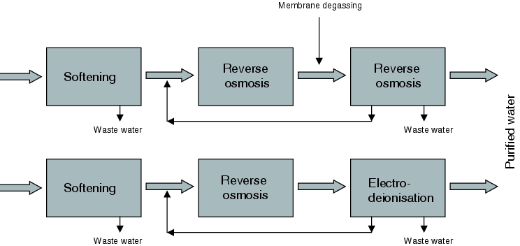
Deionisation using ion exchange technology with mixed bed technology or ultra filtration is possible. However, operational practice has shown that purification through two series connected reverse osmosis units or by a combination of reverse osmosis and electrodeionisation is preferred for the production of purified water. These procedures also guarantee a permeate conductivity of <1.1 mS/cm at 20 °C even with poor raw water qualities. The main composition of these two systems is shown in figure 5.B-8.
 |
2 Water for injection (WFI)
Water for injection (WFI) is required for the production of sterile medicinal products. The requirements of manufacturing procedures for WFI are different in the USA, Japan and Europe (see figure 5.B-9). According to the American pharmacopoeia (USP), the production of WFI via double stage reverse osmosis (see chapter 1.4 Reverse osmosis) is possible. The requirements of the physical, chemical and microbiological properties (see chapter 5.A.3 Water for injection) must of course be achieved. In Japan WFI can also be produced via ultra filtration. In Europe, however, WFI must be produced via distillation.
|
Permissible manufacturing procedure for WFI |
|
|---|---|
|
Europe |
Distillation |
|
USA |
Double stage reverse osmosis or distillation |
|
Japan |
Ultra filtration or distillation |
Based on the requirements in the European pharmacopoeia, distillation is the only possible way of producing WFI in Europe. Purified water is used as the feed water for the production of WFI. However, it is also possible to use potable water as the feed water, although this would significantly reduce the yield of WFI. More costly design of the distillation facility would also be necessary as some of the salts present in potable water evaporate at the same temperature as water. Therefore, the production of WFI from purified water is preferred.
2.1 Distillation technology
Different procedures are used for distillation. High quality WFI can be produced using all the procedures presented here. The choice of procedure depends on the volume of WFI to be produced and the desired distillate temperature.
1. Simple distillation
For small quantities, simple distillation is used. Simple distillation means that the WFI is produced in a single distillation column. The water evaporates; the resulting water steam is purified and this pure steam is condensed in a heat exchanger and cooled to the desired temperature. This type of production of WFI has the disadvantage that it uses a lot of energy. Therefore, this procedure is only used if very little WFI is required, e.g. for acceptance quantities of <50 l/h.
2. Principle of the heat pump
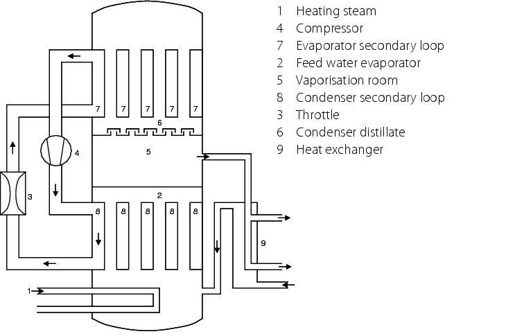 |
An economical way of producing average volumes of WFI (around 25 to 1000 l/h) is the use of the heat pump principle (see figure 5.B-10). Here, the feed water is first heated and evaporated in the lower part of the column by supplying external energy. The steam is condensed in the top part of the column. The necessary coolant has lower pressure than the steam. The steam's heat energy is withdrawn by the coolant. The steam condenses. The condensation heat is also transferred to the coolant. As the pressure in the coolant is less than in the pure medium, it evaporates. The steam from the coolant is compressed, and condenses again. This brings the coolant to a higher temperature and it becomes the heating agent for evaporating the feed water. After transfer of the heat, the heating agent is curbed again and used as the coolant for condensation for the pure steam. The flew off pure steam distillate can be used to preheat the feed water. The distillation temperature can be adjusted by the dimensioning of the necessary heat exchanger. A WFI generating facility working according to this principle can also be constructed in a different design without the use of heating agent/coolant, with the generated pure steam being used as the heating agent for the evaporator. The advantage of such a facility is the relatively low energy requirements and the variability of the temperature of the generated WFI (see figure 5.B-10).
3. Multi-stage distillation
The pharmaceutical industry primarily uses multi-stage distillation. Effective distillation is possible by using several distillation coloums in series, as the pure steam generated in each respective plant heats the next coloumn. These facilities are also easy to maintain and clean due to the lack of moving parts and the simple mechanical design, and they have a long service life.
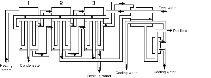
Multi-stage distillation consists of a certain number of distillation coloumns. Between the individual distillation coloumns there are heat exchangers. One or two heat exchangers are connected to the last plant. Figure 5.B-11 illustrates the composition of a multi-stage distillation facility.
 |
How it works
The first column is operated with heating steam. The pressure is at its highest in the first column. This results in a high boiling point. Some of the feed water evaporates. The resulting steam is purified in the column and leaves the first column as pure steam. The pure steam from the first column is used as the heating steam for the next column. The unevaporated feed water from the first column is used as feed water for the next column. The heating steam condensate from the first column is rejected or added to the heating steam generator. Before the feed water reaches the next column, its pressure is reduced so that the boiling point also falls. In the second column, the pure steam created in the first column heats the feed water and partially condenses in the process. The pure steam distillate pressure from the second column is reduced, evaporates as a result, and is used as the heating agent for the next column. The steam generated in this column is purified in the column and is used as the heating steam for the next column. This process is repeated in the remaining columns. In the last column, there is nearly normal pressure. The distillate from the last column and the pure steam generated in the last column are fed into a heat exchanger and cooled to the desired temperature. The coolant is the feed water for the distillation plant, as well as a small quantity of coolant for controlling the distillation temperature. In the unevaporated water in the last column, the impurities of the feed water have become concentrated. The water from the last column is therefore rejected. The feed water preheated in the cooler is fed into the first column in the counter flow through the head space of the distillation stages and gradually reheated until it reaches the first column at near to working temperature. The energy yield can be optimised by applying a heat exchanger between each column, so that the feed water is not preheated in the distillation plants but in stages by the reverse flow of the pure steam distillate.
With multi-stage distillation, the energy contained in the steam is used again as heating steam for the next stages. Therefore, the required heating steam volume for evaporating 1 kg water is significantly less with multi-stage distillation than with single-stage facilities. So, for example, the required heating steam volume of a three-stage distillation facility is only about a third that of a single-stage distillation facility. The more distillation plants are used, the more heating steam and cooling water is saved. From about the seventh column, little or no more savings are possible. The number of columns used is based on the demand for WFI.
Purification of the steam
There are two main procedures for reliable purification of the steam:
- The water is quickly evaporated through a high energy input. The pressure rises due to evaporation. The steam is thus given a very high speed. The steam is fed through a spiral fitted in the column. When the steam flows through the spiral, high centrifugal forces are achieved due to the speed of the steam. Droplets and particles contained in the pure steam are flung against the wall by the centrifugal forces. A water film forms on the wall. Gravity causes the water droplets and particles to flow back into the column mud flap. The clean pure steam is taken from the head of the column.
- The column is designed so that the water evaporates more slowly. This means fewer droplets or salts/particles are carried along from the feed water. The steam flows into the head of the column. There are two sieves in the head of the column. First, the steam flows through a coarse sieve. Droplets and particles are separates. Any remaining water droplets and particles in the steam are separated in a second, finer sieve. The pure steam can be taken from the head of the column. See also chapter 5.F Pure steam systems.
3 Purification of pharmaceutical water treatment systems
Systems for generating pharmaceutical water must be sanitised in regular intervals. The time intervals vary from a weekly to an annual cycle, depending on the system design. The selected times are shown at the latest during the performance qualification (PQ) (see chapter 5.D.7 Process validation/performance qualification (PQ)) of the system. In particular, sanitisation may be needed if the sampling results deteriorate. A distinction is generally made between thermal and chemical sanitisation.
Thermal sanitisation is carried out with hot water and is currently not possible for EDI or CDI, as the hot water sanitisation units for EDI/CDI are not yet available (manufacturers are currently working on a hot water sanitisation system for EDI/CDI). By contrast, there are reverse osmosis units that can be sanitised with hot water. This is possible depending on the membrane used. With thermal sanitisation, the units are rinsed with hot water and the number of microorganisms reduced.
With chemical sanitisation, chemical additives (e.g. chlorine, peracetic acid, H2O2) are added to the water, the systems are rinsed and in this way the number of microorganisms is reduced. Chemical sanitisation can be used for all elements of water purification. For more information see chapter 5.E.1 Procedure to reduce microbial counts.
|
Summary Purified water and WFI can be generated through different procedures. Starting with potable water, the latest procedures for purifying potable water and generating pharmaceutical water are explained. The principles as well as the advantages and disadvantages of the different procedures are dealt with. When designing pharmaceutical water purification systems, it is important to assess the raw water quality through water analysis. As raw water qualities vary greatly, combinations of purification procedures must be based on the raw water quality. |
