|
Here you will find answers to the following questions:
|
4.I.1 Introduction
The increasing expansion of production capacities and increasingly detailed quality management require extensive automation in the production of pharmaceutical and cosmetic products. This in turn means that production must be carried out in closed systems, the manual influence of the operating personnel on controlling the processes is reduced to a minimum and operating errors can be therefore ruled out. For compliance with the quality guidelines, this not only applies to the actual production process of the pharmaceutical products, but increasingly also to the associated cleaning processes. Here, economic aspects as well as specific cleaning validation requirements must be taken into consideration.
Standing times, whatever may cause them, are unproductive. With a continuously increasing cost awareness, the personnel-intensive and time-intensive manual cleaning process is compared critically with automatic cleaning processes. Also, with closed facilities, fundamentally more aggressive cleaning conditions - type and concentration of the cleansing agent, temperatures, pressures, etc. - can be applied than with the customary methods (see chapter 8.B.3 Validating manual and automated cleaning procedures).
4.I.1.1 Definition
The quality of the product depends on the cleaning of the process equipment. Cleaning is the first and last step in any production. DIN 11483 defines "Cleaning-In-Place" as:
"CIP is the cleaning of systems without having to dismantle them and without making significant changes to the usage status of the system."
In order to be able to carry out this type of cleaning effectively and safely, it is absolutely necessary that cleanability by means of a CIP process is taken into account already when planning the process equipment.
4.I.1.2 Cleaning mechanisms
Four essential influencing factors, which exert a crucial influence on the cleaning result, are to be taken into account for cleaning process equipment (see also figure 8.B-1):
- Temperature of the cleansing solution
The temperature range required for cleaning is based on the technical possibilities, the obstinacy of the contamination/product residue to be removed and the chemical composition of the cleansing agent - Mechanical effect of the pumped cleansing solution
Here, the physical conditions required for cleaning, such as pressure, volume flow and flow rate are considered.
To achieve turbulent flow ratios, the flow rate should be at least 2m/s (or Re > 8000). - Chemical activity of the cleansing solution
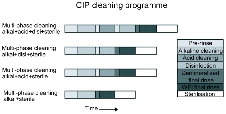
The composition, concentration, surface tension and dispersion ability are the parameters that influence the cleaning process. The type and concentration of the cleansing agent to be used depends highly on the type of contamination. In addition, the sequence and combination of different cleaning steps play an important role (see figure 1). - Total duration of effect of the cleansing solution
The chemical processes for dissolving dirt (e.g. dissolving stone with acid), dirt accumulation (e.g. dried-on starch and protein residues), saponification (e.g. for fats), dispersion and rinsing are subject to time laws.
Not all parameters must be constant during the cleaning process. The cleaning process can be optimized by making special changes to individual parameters.
Taking into account the type and level of contamination or product residues, an advance decision must be made on the deployment parameters of these influencing factors, already during the planning phase for a CIP facility.
 |
4.I.2 CIP systems
In systems engineering, a distinction is generally made between two types of CIP systems which have specific advantages and disadvantages depending on the intended use.
4.I.2.1 CIP facility for stack cleaning
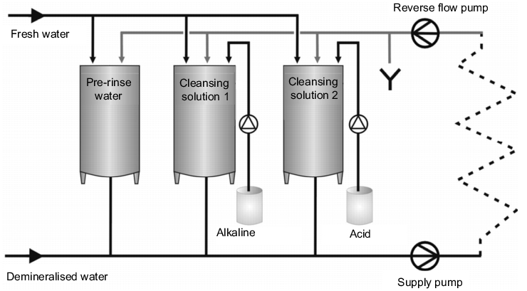
The main feature of stack cleaning is the repeated usage of the rinsing water and the cleansing solutions. Depending on the cleaning plan, the facility usually consists of a pre-rinse container, an alkaline solution container and/or an acid container with cleansing solution in the concentration required for use, and possibly a disinfectant container, i.e. so-called stacking tanks (see figure 2). The required container sizes are determined by the volume of the largest cleaning cycle.
Cleaning begins with a pre-rinse step in which the relatively clean final rinse water from the last cleaning cycle, which has been collected in the container for pre-rinse water, is used. The cleansing solution is conveyed through the process equipment via a supply and reverse flow pump, with the stacking tanks often being included in the circuit.
This is followed either by pure alkaline cleaning or an alkaline/acid cleaning process, possibly with intermediate rinsing steps. Using a suitable measuring technique (see chapter 4.I.3.6 Requirements for measuring instruments) the phases of the individual cleansing solutions are separated in the reverse flow to the stacking tanks, e.g. water - alkaline solution or alkaline solution - acid, and the cleansing solutions are conveyed to the respective tanks. In addition, an initially dirty part of the cleansing solution can be rejected specifically into the waste water. The last rinsing step is always carried out with the water quality that is required in the production process, e.g. drinking water in acc. with DVGW, purified water or WFI (see chapter 5 Pharmaceutical Water)
 |
.
Advantages of stack cleaning:
- Minimised water and cleansing agent consumption and reduced energy costs through multiple use of the solutions/rinsing water
- Short-term availability of the cleansing facility through the stacked cleansing solutions; only the final rinse water is taken directly from the operating network
- Shorter cleaning times through more highly concentrated cleansing solutions
Disadvantages of stack cleaning:
- Residue particles from previous cleaning processes can accumulate in the stacking tanks ® Hazard of cross-contamination if several items of process facilities are cleaned with a CIP facility
- Higher effort required for systems engineering on the CIP facility
- Validation takes longer and results in higher costs
4.I.2.2 CIP facility for lost cleaning
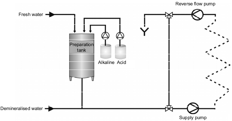
Disposable cleaning is characterised by the fact that a fresh solution is used for each cleaning step. The cleansing solution is pumped into the process equipment in a short circuit, i.e. not using the stacking container, and rejected into the waste water system after cleaning. There are two versions of disposable cleaning that can be installed,
- with containers in which the ready-to-use cleansing solution is stored (see figure 3), or
Figure 3 Disposable CIP with stacking containers
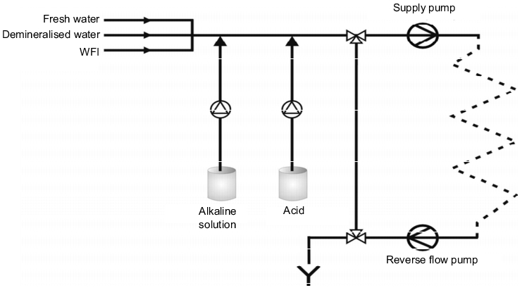
- without containers, where the solution is generated "online" by dosing the cleaning concentrate directly into the circulation line (see figure 4).
Figure 4 Disposable CIP with online dosage
Advantages of lost cleaning:
- The cleansing solutions are not burdened by the residue particles from previous cleaning processes and have a constantly consistent cleaning effect.
- Each cleaning step can be specifically parameterised for any different cleaning requirements (e.g. concentration, temperature).
- Especially with the "online" variant, there are reduced costs in terms of system engineering.
- Validation is easier to carry out.
Disadvantages of lost cleaning:
- The consumption of water and cleansing agents and the energy costs are high due to the one-off use of the solutions/rinsing water.
- Cleaning times are increased due to the lower concentration of the cleansing solutions required by the procedure.
- The cleaning duration, especially with the "online" version, depends on the availability of the waters used.
In the pharmaceutical industry, lost CIP cleaning is in practice preferred to stacked cleaning, as the risks of cross-contamination are minimised and the cleaning processes are easier to validate.
Through in-depth analysis and consideration of the requirements of a cleaning system, taking into account the needs from the production process, however, it is possible to achieve the optimum product safety, quality, investment means and operational costs.
4.I.3 GMP-conform design of CIP facilities
As CIP facilities are directly connected to the process equipment, at least during cleaning, it goes without saying that the same execution requirements apply to these as to the process equipment itself. (See chapter 4.B Mechanical components)
The technical design of the facilities is described in many bodies of rules, including the EU GMP Guideline. This stipulates detailed hygiene requirements for premises and equipment, i.e. also for components and facilities, and specific reference is made to the fact that they must be "easy to clean". They must be designed, constructed and used with a view to minimising risks and achieving thorough cleanability so that any contamination, cross-contamination or quality impairment of the product is prevented.
The principles of hygiene-compliant construction are given in the guidelines on QHD qualification (Qualified Hygenic Design). This deals with a test system developed for hygiene-compliant construction [QHD Manual] by the VDMA's "Department for Sterile Process Technology". The test system is split into 2 test phases:
- Phase I: Theoretical proof of hygiene-compliant construction
- Phase II: Proof of the practical cleanability via a standard test
4.I.3.1 Influences of the surfaces
The main effects that lead to hygienic problems can be avoided through the knowledge of the behaviour of microorganisms and microsubstances in facilities and components. A significant cause is the extremely large adhesive power that is exerted between small substances or microorganisms and surfaces. If the surface rawnesses are less than the size of the particle, the cleansing agent can directly wet and destroy the microbiological contamination during cleaning. If the surface rawnesses are larger than the particles, the microorganisms are no longer directly reached, but only after the cleansing agent has been given a sufficiently long diffusion time. If the cleaning times are too short, contamination is left behind. This problem is even more critical for narrow slits (e.g. seals), where the cleaning effect is difficult to achieve and microorganisms find ideal conditions for reproduction.
From these considerations, it is easy to deduce the most important requirements for the different facility components, although only the most important components are specified here, as these requirements can also be easily transferred to other facility components.
4.I.3.2 Requirements for pipes and tanks
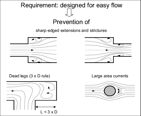
Pipes and containers in pharmaceutical process equipment take up the biggest percentage surface area and are therefore particularly critical in terms of their technical design. Surfaces should cause little mechanical damage to the product and should have a low bonding capacity for external particles. Their roughness, as a living space for microorganisms and sediments for substrates should be as low as possible and the contours should be rounded. (See chapter 1 Construction and installation materials). figure 5 gives an overview of the requirements.
|
Requirements for pipes and tanks |
|---|
|
 |
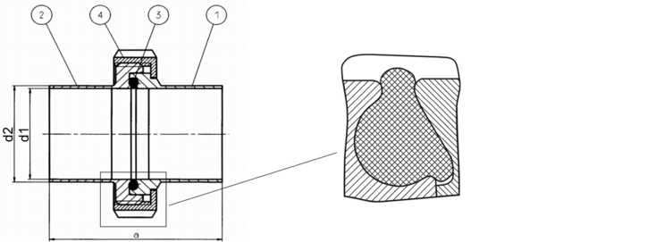
4.I.3.3 Requirements for bonding elements and seals
Seals present a particular source of hazards. On the one hand, this is caused by the materials themselves, and on the other hand, standard constructions are often used to construct the equipment, without taking into account the associated infection hazards. Therefore, the requirements specified in figure 7 apply in particular.
|
Requirements for bonding elements and seals |
|---|
|
 |
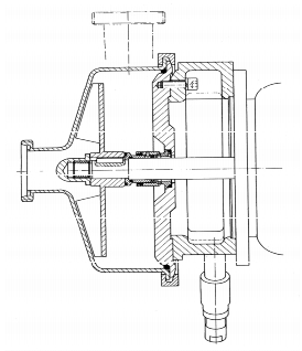
4.I.3.4 Requirements for pumps
In the field of pumps, the draft of "DIN EN 12462 Biotechnology" already laid down the first precise definitions of the cleaning and sterilisation capability, the tightness of the materials and their surfaces and constructive details in terms of the CIP/SIP capability (see figure 9). Figure 10 shows a cross-section of a hygiene-compliant pump.
|
Requirements for pumps |
|---|
|
 |
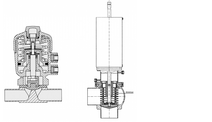
4.I.3.5 Requirement for valves
Special requirements are made of valves in automated pipe networks. Often, the main task of such fittings is to act as switch modules to interrupt or release the flow in pipes, in order to separate or connect facility areas from or with each other.
In order to be able to safely separate mutual contact of a product or cleansing agent in a pipe network, for example, the principle of double sealing with a leakage cut-out is today state-of-the-art for valves. Here, in addition to safeguarding contact between the different products, the mechanics of the valve are also separated from the liquid by bellows and are thus easy to clean.
Parallel to this complex valve technology, however, diaphragm valves are also increasingly being used in systems engineering. The diaphragm valves are very easy to clean due to their design, and can be used for almost any task.
Examples of hygienic valves are shown in figure 11.
 |
4.I.3.6 Requirements for measuring instruments
Control equipment and sensors are fitted in the facilities to control and regulate the production process and to keep it externally transparent. Cleanability and sterilisability in the CIP/SIP procedure is just as important as the regulated function of the equipment, i.e. it must be possible to clean and sterilise the measuring equipment with no residue. Given this premise, the recording fitting of the measuring instrument is given particular importance. In particular, the points in figure 12 must be taken into consideration.
|
Requirements for measuring instruments |
|---|
|
4.I.4 Nozzle heads for container cleaning
Nozzle heads are generally used to apply the cleansing solutions to the container walls when cleaning facilities, especially containers. Their design and version differs according to the required purpose. The type, shape, performance, positioning and number of nozzle heads must selected from an engineering perspective and taking into consideration the points specified in figure 13, as the hydraulics, consisting of the nozzle head and cleaning pumps, are an important factor for successful cleaning.
|
Factors for successful cleaning |
|---|
|
The nozzle heads are installed so that a sufficient flow volume reaches the upper and lateral tank walls. While nozzle heads that are too low will not achieve a sufficient upwards spray width of the spray jet, if the nozzles are positioned too high, the spray will be so strongly reflected by the unfavourable angle of deflection that the falling cleansing solution could spoil the entire spray pattern of the nozzle head.
However, the aim is to achieve the best possible cleaning with all types of nozzle heads, specifically in very contaminated areas. The lower area is usually etched and removed by the receding cleansing solution.
A distinction is made between the following kinds of nozzle head:
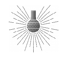
4.I.4.1 Spray ball
- Low pressure cleaning principle
- Fixed nozzle head
- Variable spray patterns through different bore patterns in the head
- For readily soluble dirt residues
- High flow with low pressure
For an illustration of the spray pattern, see figure 14.
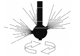
4.I.4.2 Rotating nozzle head
- Low pressure cleaning principle
- A targeted, rotating fanned jet in one level, driven by a flow gear
- Individual nozzle layout on the nozzle head
- Higher cleaning effect with lower water consumption compared with the spray ball, due to lower overall outlet area
For an illustration of the spray pattern, see figure 15
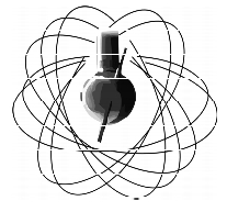
4.I.4.3 Targeted jet/orbital cleaner
- Low and high pressure cleaning principle
- Rotating, sharply bundled cleaning jet in two levels, usually driven by an electric motor
- Special outlet cross-sections prevent vaporisation of the cleansing solution
- Defined friction tolerances achieve a self-cleaning effect of the nozzle head.
- High cleaning effect with minimised consumption of cleansing solution
- To achieve overall coverage of the container walls, a minimum running time must be adhered to.
- Function monitoring possible -> Validation
For an illustration of the spray pattern, see figure 16..
 |
 |
 |
|
Figure 14 |
Figure 15 |
Figure 16 |
4.I.5 Measuring technology
From a qualification and validation perspective, the reproducibility of automatic cleaning has advantages over a manual cleaning process that depends on the person. Cleaning-related parameters can be recorded and documented sooner and more easily and are thus more easily accessible for validation. To this end, the following parameters are usually measured and documented online in modern CIP facilities. Measuring value:
- Flow Q
- Pressure p
- Temperature T
- Conductivity k
4.I.5.1 Flow measurement
The flow is usually used as the supply value for the CIP pump control in the supply and reverse flow in order to guarantee that there is always a sufficient flow rate (v > 2 m/s, Re > 8000) in the pipes.
Measuring instruments with a magnetic inductive measuring principle and mass flow measuring instruments with the Coriolis measuring principle are suitable for measuring the flow. It must be ensured that a minimum conductivity of at least k > 4 mS is given for magnetic inductive measuring procedures. If demineralised water is used in a CIP procedure, this measurement type cannot be used. A further measuring method, though far below the aforementioned methods in terms of precision, is flow measurement by ultrasound. However, this does offer the advantage that it can be applied to the pipe from outside and thus, from a GMP perspective, is the most hygienic volume measurement.
If the flow measurement is defined as a critical measuring instrument for qualification or validation, the mass flow measuring instrument should be given priority due to the precision of the measurement. For calibration of the measuring instrument, it must be ensured that not only the measurement transmitter itself, but also the output signal for control (pulse signal, flow signal) is checked.
4.I.5.2 Pressure measurement
The pressure measurement in CIP systems is used both as a critical measuring instrument for process monitoring and as a safety measuring instrument. In particular for nozzle heads, compliance with a defined pressure range must be ensured, both minimum and maximum, in order to guarantee the desired spray pattern for optimal cleaning of a container. The pressure measurement is often used to monitor and measure the level in pressurised containers, as a safety precaution.
The main type of pressure measuring instruments used are measurement recorders with diaphragm pressure gauges, which are filled with different utilities depending on the requirement (temperature and pressure range). They are installed in hygienic screw fittings or clamp connections and follow the GMP Guidelines. If the measuring values are not only used for display, but are also evaluated in the CIP control, then electrical measurement recorders are used. These are coupled in the process in the same way as manometers with the diaphragm pressure gauge. Recently, electrical pressure transmitters with ceramic surfaces have also been used, which do not require diaphragm pressure gauges.
If a pressure measurement is classified as a critical value, it is recommended that the pressure measurement be carried out electrically in order to be able to record and evaluate the values in the control. Long before cleaning due to a falling pressure level is no longer sufficient, trend analyses of measurement values often make it possible to detect this as a fault.
4.I.5.3 Temperature measurement
For the cleaning effect, but more so for steam sterilisation, compliance with the required temperature at specific points of the cleaning facility is a quality-related criterion and is usually also classified as a critical measurement value.
Temperature is now measured almost exclusively with PT-100 thermocouples which are installed in special fitted sleeves or immersion sleeves. The speed of the temperature changes in the process and the associated need to measure the temperature just as quickly, is crucial for the design of the immersion sleeves. The immersion sleeves are welded into the pipe or container and are thus installed with no slits or leaks.
To measure the temperature to ensure a correctly executed sterilisation, the temperature sensor is to be positioned at the coldest spot of the facility.
4.I.5.4 Conductivity measurement
Measurement of the conductivity of liquids is used in CIP procedure for several requirements of plant control. On the one hand, it is used to determine the concentration of cleaning solutions, as the conductivity changes with the increase or decrease in concentration, and on the other hand, it is used to separate the phases of the individual cleaning steps (see chapter chapter 4.I.1 Introduction). In particular, the measurement of the final rinse conductivity after cleaning, i.e falling below a minimum conductivity level (usually k < 1 to 3 mS), is most important for the subsequent production process.
A distinction is made between conductive and inductive measuring procedures. As the cell constant can be relatively easily minimised in conductive conductivity measuring instruments due to their structural design, these instruments are preferred for the lower measuring range, e.g. demineralised or WFI water. Inductive instruments, due to their design, are almost maintenance-free, can be easily calibrated and, due to the inductive measuring procedure, are insensitive to electrode abrasion and build-up of deposits.
4.I.6 Realisation of cleaning systems
 |
To ensure realisation of a GMP-conform cleaning programme, the exact cleaning target must first be defined. The cleaning target gives a required value to be achieved for the later qualification and validation (see chapter 8.E Acceptance criteria and limit calculation).
|
Checklist for realisation of cleaning projects |
|---|
|
What should be cleaned?
|
|
What production residues, contamination are present? |
|
What cleaning steps must be provided for? (see figure 1)
|
|
How should cleaning be carried out?
|
|
Visualisation of the process (CIP validation by PC) |
|
Is the CIP system working to full capacity for the intended project plan?
|
|
What disassembly stages are planned in production, for which the CIP system should also be used? |
|
Is there a plant standard for components?
|
|
What utilities supply is necessary?
|
In order to achieve a cleaning target, exact knowledge and analyses of the objects and production residues to be cleaned are required. The cleaning selection is based on the prescribed products and procedures from a GMP perspective (figure 18). Only detailed knowledge of the production processes allow selection of the chemical cleansing agent and cleaning process. Checklists for querying the conditions (see figure 18) help in the selection of the best cleaning variants, also from an economic perspective.
|
Summary Knowledge of the different kinds of procedures and functionalities is necessary to realise a GMP-conform CIP facility. Procedures, chemicals and spraying steps, through to the measuring and control technique, are selected. For CIP systems, a distinction is made between stacked cleaning (re-use of the cleansing solution) and disposable cleaning (one-off use of the cleansing solution). The same requirements apply to the design of CIP facilities as to the process equipment: dead volume-free design of the components, smooth surfaces and turbulent flow in the pipes. The type, shape, performance, positioning and number of nozzle heads decides on the level of success of the cleaning. The advantage over manual cleaning is that cleaning-related parameters such as flow, pressure, temperature and conductivity can be measured and included in qualification and validation. |
