|
Here you will find answers to the following questions:
|
3.H.1 Introduction
Pharmaceutical rules and specifications often contain very precise but also generally formulated requirements of air conditioning technology, such as "temperature, humidity and ventilation of premises should be adequate". This generally formulated requirement is partially substantiated in the supplementary guideline of the EU GMP Guideline for the manufacture of sterile products, for example.
The following chapters give a practical description of the extensive, and sometimes complex field of air conditioning technology in terms of the requirements that result from the pharmaceutical environment in question.
The term air conditioning technology and its further sub-divisions are described in DIN 1946/Part 1. Two basic types are distinguished by the terms room ventilation technology and process air conditioning technology. Both types are found and required in the pharmaceutical manufacturing sites. The essential task of a ventilation system is to guarantee the desired room conditions, such as temperature, humidity and cleanliness. In contrast, the process air systems must guarantee the required process parameters.
Figure 3.H-1 shows the structure of the term "air conditioning technology" (extract from DIN 1946/Part 1) with reference to deployment in the pharmaceutical manufacturing sites.
|
|
||
|
1. Belong to the equipment in the pharmaceutical manufacturing sites, e.g. fluid bed spray granulation, drying processes, coating processes 2. Both types of ventilation systems "with" and "without" ventilation functions, as well as a combination of both are found in the pharmaceutical manufacturing sites 3. Not represented in the pharmaceutical manufacturing sites |

In the air conditioning technology structure, a distinction is made between ventilation systems with and without ventilation functions. The term ventilation function means that the air in the room is exchanged with external air. The further sub-structure shows the number of thermodynamic air handling functions with which the ventilation system is equipped.
The thermodynamic air handling functions shown in figure 3.H-2 apply for the preparation of the inlet air: heating, cooling, humidifying and dehumidifying.
|
Classification of room ventilation systems |
Ventilation |
Recirculating |
Partial air |
Recirculating |
Air conditioners |
Recirculating |
|---|---|---|---|---|---|---|
|
Number of thermodynamic air handling functions |
None or one |
Two or three |
Four |
|||
The terms for classification of ventilation systems do not provide any information on the filtering of the inlet air.
The next chapters deal exclusively with room ventilation facilities. No detail is given of the engineering-related planning of ventilation systems, but instead the focus is placed on the fundamental design, planning, solution options and implementation in terms of the pharmaceutical requirements.
3.H.2 Room ventilation systems
The room ventilation systems are designated according to the available thermodynamic air handling functions in a ventilation system (acc. to DIN 1946 / Part 1, see Figure 3.H-2 classification of ventilation systems).
The respective design and structure of the ventilation systems results from the requirements and conditions made of the ventilation system. (See chapter 3.H.4 Principles for the design and planning of air conditioning ventilation systems.)
The following criteria can play a role in the selection of the system to be used:
- Influence of outside air
- Climatic conditions of site
- Operational costs of the different systems, especially the costs for energy consumption: current, heat, cold (cooling, dehumidification) and humidification
- Cleanliness requirements
- Flexibility
In pharmaceutical manufacturing, essentially the following ventilation systems are used:
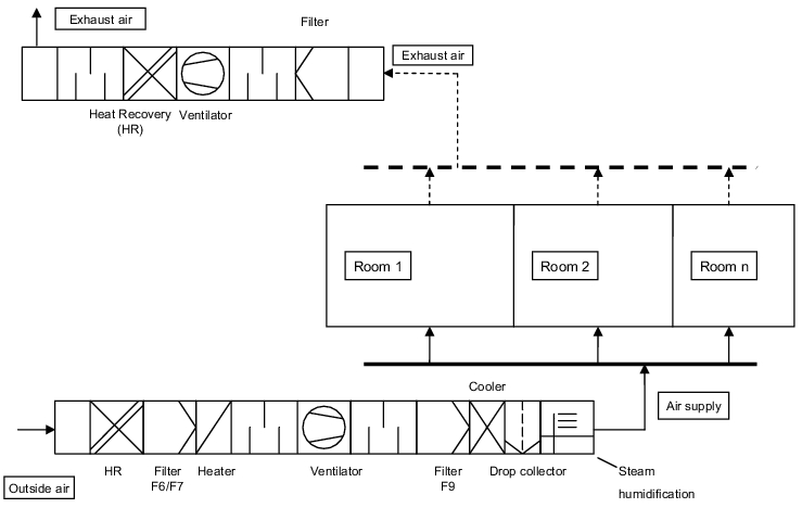
3.H.2.1 Pure (100%) external air conditioning system
The inlet air to the rooms always consists of 100% external air. The external air is prepared in the ventilation system according to the defined conditions (temperature, humidity, purity). With a pure external air facility, impurities/contamination cannot enter the inlet air system via the exhaust air system. When using a heat recovery system, it must be ensured that the two systems cannot be connected via the heat recovery components (figure 3.H-3).
|
|
Pure external air conditioning system are used with the following conditions:
- Supply of different production areas through a joint ventilation system
- The exhaust air from the rooms is so highly contaminated with impurities that no safe elimination of impurities is guaranteed by the cleaning/filter phases of the ventilation system.
- Flexibility is required, i.e. at any time, a manufacturing site for a different product group with other requirements can be supplied without a risk of cross-contamination
3.H.2.2 Central recirculating air/mixed air conditioning system
The inlet air to the rooms consists of some external air and some recirculating air. The share of "external air" and "recirculating air" can be fixed or can be variable according to the external temperature. Corresponding to the number of people working in the manufacturing site, a minimum external air share must not be undershot (figure 3.H-4).
Central recirculating air/mixed air conditioning system are used with the following conditions:
- Supply of one production area (dedicated equipment)
- The concentration of impurities in the exhaust air from the rooms is low enough that safe elimination of the impurities is guaranteed via the cleaning/filter stages of the air technology system.
- Direct heat recovery without additional heat exchanger (low investment costs)
- No flexibility, i.e. a manufacturing site for a different product group with other requirements cannot be supplied without a risk of cross-contamination.
|
|

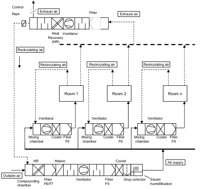
3.H.2.3 Decentralised recirculating air/mixed air conditioning
system with central external air preparation
The air supply and exhaust air of a room or a zone is conveyed via a recirculating air facility. Conveying centrally-prepared external air guarantees the required external air share for the persons in the rooms (figure 3.H-5).
The recirculating air facility is usually fitted with a condenser and a filter stage.
Decentralised recirculating air/mixed air facilities with central external air preparation are used with the following conditions:
- Supply of different production areas through a joint external air preparation system
- The concentration of impurities in the exhaust air from the rooms is so low that safe elimination of the impurities is guaranteed via the cleaning/filter stages of the decentralised recirculating air facility.
- Flexibility, i.e. a manufacturing site for another product group with other requirement can be supplied at any time if the central external air preparation is carried out with a "pure external air plant".
|
|
3.H.2.4 Pure recirculating air conditioning system
The air supply and exhaust air of a room or a zone is conveyed via a recirculating air facility. No prepared external air is supplied. The pure recirculating air facility is therefore only used for areas which are not permanently staffed and where the inlet of external air could influence the air quality (figure 3.H-6).
Typical applications are partially high-quality clean room zones in a clean room, e.g. zones of cleanliness class A in a sterile room, LF work benches.
|
|
3.H.2.5 Systems for tempering and volume flow regulation
The following two systems have proven their worth in practice for tempering and volume flow regulation:
- Single duct system: Temperature regulation takes place either by room or by zone via post-heating registers or aftercoolers. The air currents (air volume) are today usually configured or regulated with volume current regulators. With constant air currents, a very simple setting can be made via throttles such as flaps and perforated plates (figure 3.H-7).
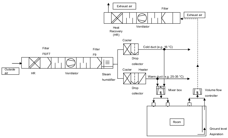
- Dual duct system: After the central air preparation facility, the inlet air is split across two differently tempered air supply ducts. The air in the warm duct is heated to a temperature of 25 to 35 °C, while the air in the cold duct is cooled to 15 to 18 °C, for example. Before a room or zone, the two air flows are mixed in a blending box according to the required room temperature and heat burden, and blown in as inlet air. With the blending boxes, you can set constant air currents (air volume) or variable volumes (figure 3.H-8).
Figure 3.H-7 Room supply with a single duct system
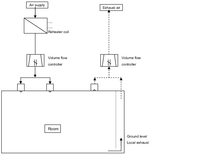
Figure 3.H-8 Room supply with a dual duct system
3.H.2.6 Control-systems of the air volume flows
In principle, a distinction is made between a constant or variable inlet and exhaust air current supply for individual rooms, zones or areas. The two supply strategies differ as shown in figure 3.H-9.
|
Constant air volume flow |
Variable air volume flow |
|---|---|
|
A fixed volume current is set via a constant volume current regulator, blending box, flap or other throttle. With a single duct facility, temperature regulation takes place either by room or by zone via post-heating registers or aftercoolers. |
Depending on the heat occurring in the room or in a zone and/or the activity, the air volume currents (inlet and exhaust air) can be raised from an initial value to a maximum value, e.g. via the temperature regulation. With decreasing heat and/or activity, the air currents are reduced to the initial value again. |
|
Advantages:
|
Advantages:
|
|
Disadvantages:
|
Disadvantages:
|
3.H.2.7 Utilities for the operation of room ventilation systems
Different kinds of energies (and utilities) are required to operate ventilation systems, in order to convey the air, filter it and enable thermodynamic air handling functions such as heating, cooling, dehumidifying and humidifying. Energies that are used for heating, cooling and dehumidifying do not usually have any direct contact with the air to be prepared. The air is passed through heat exchangers which are equipped with lamellas on the air side. The energy supply is via pipes that are connected to the lamellas.
The essential energies (and utilities) used in ventilation systems are described in figure 3.H-10.
|
Physical or thermodynamic functions |
Type of energy or utility |
|---|---|
|
Air delivery |
|
|
Heating |
|
|
Cooling/dehumidifying |
|
|
Humidifying |
|
3.H.3 Filters
To realise the required air quality and conditions in the premises of a pharmaceutical manufacturing site, different standard components are used to configure an air technology system.
The required purity of the air in the premises can only be achieved with effective cleaning of the external air or recirculating air. This requires a suitable, correctly designed filter.
Air filters are components with which particles and gaseous impurities are filtered and separated from the air. The ambient air is penetrated by different substances of different particle sizes and different materials. This mixture of ingredients must be cleaned by suitable filters so that the required cleanliness conditions are complied with in a manufacturing site.
Separation in the air filters (filter medium) is based on different physical effects (see figure 3.H-11).
|
|
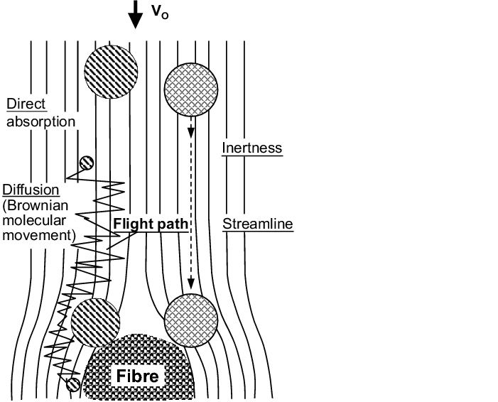
The most important separation effects are
- Diffusion effect: The diffusion effect is a consequence of Brownian molecular movement and is therefore only effective for very small particles. The molecular movement causes a diffuse movement of the particle along a virtual streamline. It is separated at the fibre if it remains sufficiently close to the fibre for a long enough time.
- Inertness effect: The inertness effect causes separation at the fibres if the particle is of a particular size and thus cannot follow the course of the streamline.
- Blocking effect: The blocking effect always occurs if a particle is on a streamline whose distance from the fibre during circulation is less than half the particle diameter.
- Sieve effect: The sieve effect only occurs for a particle whose diameter is greater than the free cross-section between the fibres (pore width).
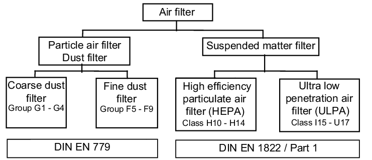
The different filter qualities are split into coarse, fine and suspended matter filters according to the separation capacity of the different particles. This division is based on standardised testing procedures. Today, following many intermediate steps, the following two valid European standards for air filters
- DIN EN 779 Particle air filter for general ventilation
- DIN EN 1822-1 Suspended matter filter (HEPA and ULPA) are the specifications and testing bases for all filter manufacturers.:
Figure 3.H-12 Structure of the air filter in accordance with DIN 24183 (E) Part 1
3.H.3.1 Particle air filter
The particle air filters are classed in "coarse (C1 to C4)" and "fine (F5 to F 6)" filter groups in accordance with DIN EN 779 (see figure 3.H-13).
|
Initial effectiveness (EA) |
EA < 20% |
EA ³ 20% |
|
|---|---|---|---|
|
Characteristics |
Average separation rate Am (%) |
Average effectiveness Em (%) |
|
|
Filter group |
Filter class |
Class limits |
|
|
Coarse (C) |
g1 g2 g3 g4 |
Am < 65 5 Ј Am < 80 80 Ј Am < 90 80 Ј Am |
- - - - |
|
Fine (F) |
f5 f6 f7 f8 f9 |
- - - - - |
40 Ј Em < 60 60 Ј Em < 80 80 Ј Em < 90 90 Ј Em < 95 95 Ј Em |
|
Am = Average separation rate compared with synthetic dust Em = Average effectiveness compared with atmospheric dust |
|||
For pharmaceutical manufacturing sites, the coarse filters are irrelevant as the separating power of these filters is too low to achieve the required purity, total effectiveness of the filter > 95 %. This total effectiveness can only be achieved with fine filters in the 1st and 2nd filter stage of air technology equipment.
The following combinations of filter classes are today used for two filter stages in series:
- 1st filter stage F 6 or F 7
- 2nd filter stage F 9
With this filter combination, the following targets are achieved:
- Total effectiveness > 95%
- High period of use of the filter
- Manageable energy costs
With all mechanical filters, it must be taken into account that the separation power is not constant, but changes due to the following factors:
- Fluctuating dust content of the external air: Due to the season (e.g. pollen in spring) and environment (e.g. emissions of hazardous substances from neighbouring plants), the dust content of the external air fluctuates.
- Velocity at which the air passes through the filter medium: With a reduced volume flow in relation to the test volume flow, the separation rate tends to increase.
- Filter cakes: With the increasing contamination (build-up of a filter cake) of the filter, the separation rate increases due to the additional filtration through the collected dust.
- Air humidity: In hygiene areas, the air filter should be prevented from dropping below the dewpoint, as bacteria and fungus growth is encouraged near the dewpoint. The relative air humidity of the air flushing through should therefore not exceed a maximum value of 95 %.
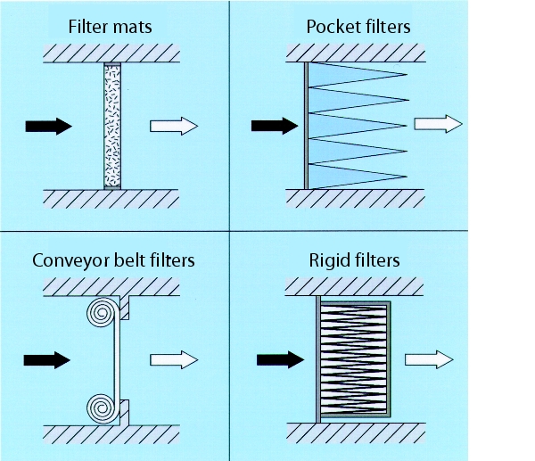
The filter media used consist of fibreglass or synthetic-organic fibres, which are then connected thermally or chemically with binding agents. The following models are generally used (see figure 3.H-14):
- Filter mats ® Filter classes C1 to F 6
- Conveyor belt filter ® Filter classes G 1 to F 5
- Pocket filter ® Filter classes C1 to F 9
- Cassette filter ® Filter classes F 5 to F 9 (rigid filter)
|
|
Today, the separation rate or effectiveness of the particle air filters is determined as a percentage in comparison with "atmospheric dust" or "synthetic dust", without producing a reference to a particle size.
The first investigations and standardisation activities aim to determine a fractional separation rate for a defined particle size for the comparison of the efficiency of a particle air filter.
|
|

|
|

The diagram (see figure 3.H-16) shows a comparison of the separation rate (%) for the different particle sizes by pocket filters with different filter classes. At present, the fractional separation rate should be calculated according to the Eurovent draft standard with a particle size of 0.4 mm.
3.H.3.2 Suspended matter filter - HEPA-Filter
For clean rooms with defined particle counts in the room air, usually a 3rd filter stage must be provided for in addition to the two particle air filter stages. As the 3rd filter stage, the suspended matter filter should be fitted as near as possible to the end of the room, i.e. just before the entry of the inlet air into the clean room.
With suspended matter filters, dust, suspended matter and aerosols can be separated in a range up to 0.1 mm.
For the specification of the suspended matter filter, the different national standards were transferred into a European standard "DIN EN 1822/T 1- 5" (see figure 3.H-17).
|
DIN EN 1822 Suspended matter filter (HEPA and ULPA) |
||
|---|---|---|
|
Part |
Title |
Status/Valid |
|
1 |
Classification, performance test, labelling |
July 1998 |
|
2 |
Aerosol generation, measuring instruments, particle count statistic |
July 1998 |
|
3 |
Check of the planned filter medium |
July 1998 |
|
4 |
Leak test on the filter element (scan procedure) |
Open |
|
5 |
Separation rate test of the filter element |
Open |
According to the above-mentioned DIN standard, suspended matter filters have the filter classes illustrated in figure 3.H-18 with the associated filtration performances.
|
Filter |
Integral value |
Local value |
||
|---|---|---|---|---|
|
Separation |
Forward |
Separation rate |
Forward |
|
|
h10 |
85 |
15 |
- |
- |
|
h11 |
95 |
5 |
- |
- |
|
h12 |
99.5 |
0.5 |
- |
- |
|
h13 |
99.95 |
0.05 |
99.75 |
0.25 |
|
h14 |
99.995 |
0.005 |
99.975 |
0.025 |
|
U 15 |
99.999 5 |
0.000 5 |
99.997 5 |
0.002 5 |
|
U 16 |
99.999 95 |
0.000 05 |
99.999 75 |
0.000 25 |
|
U 17 |
99.999 995 |
0.000 005 |
99. 999 9 |
0.000 1 |
|
HEPA filter (H) => High Efficiency Particulate Air Filter |
||||
To assess the suspended matter filters, a testing procedure was defined in DIN EN 1882 in which the separation rate is determined in the separation rate minimum. The physical basis is the characteristic minimum curve which describes the separation behaviour of fibre filters and thus also of suspended matter filters (see figure 3.H-19). The minimum lies in the transition area between stochastic movement (diffusion) through Brownian molecular movement and inertness effect as the determining separation mechanisms.
|
|
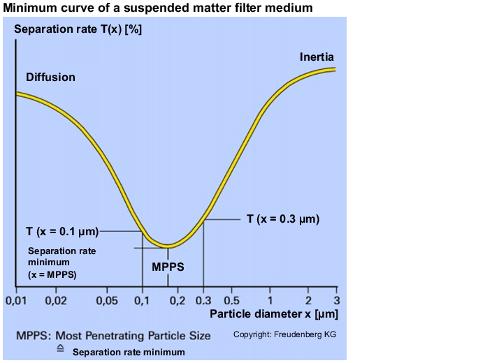
The position of the suspended matter filter's separation rate minimum, both in terms of the percentage separate rate and also of the particle size with the highest penetration, depends on the velocity of the air flow through the filter medium. The particle size with the highest penetration for a defined filter medium flow velocity is called the Most Penetration Particle Size (MPPS = separation rate minimum).
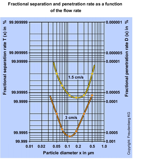
Through the connection between the filter medium flow velocity and separation performance, the separation performance of a suspended matter filter can be increased by reducing the medium velocity (see figure 3.H-20).
|
|
The determination and assignment of the individual suspended matter filters to the filter classes is carried out in accordance with DIN EN 1822. Here, the suspended matter filters of classes up to H 14 can be tested with the so-called oil strand test. As of filter class U15, a leak detection of the particle count method must be carried out, although the particle count method is already advisable even as of filter class H 13.
Leakage test
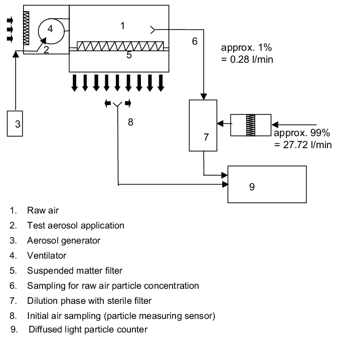
With the oil strand test, a leak is visually detected, in that the filter element is acted upon by a high concentration paraffin cloud at the raw air side and a tester checks if identifiable oil strands are present at the pure air side. Every identified oil strand indicates the position of a leak (figure 3.H-21).
|
|
The leak detection and separation rate determination using the particle method has the following advantages:
- High precision of the measurements
- Determination of the total separation rate in the separation rate minimum
- Determination of the local separation rate
- Determination of leak positions
For the particle method, DIN EN 1822 prescribes the following procedure:
- Determination of the Minimum Penetration Particle Size (MPPS) with a defined filter medium flow velocity on a flat filter medium
- Fully scan the finished filter element with specified volume flow using MPPS particles
- Calculation of the integral and local separation rates
- Classification of the filter in the corresponding filter class
The test methods described in DIN EN 1822 can be implemented by the filter manufacturers with corresponding test benches. The tests cannot usually be fully implemented when testing fitted suspended matter filters.
The test structure shown in figure 3.H-21 is possible when using the particle count method for fitted suspended matter filters:
- The test aerosol is applied to suspended matter filter at the raw air side of the filter as follows.
- LF unit: The aerosol is applied via the ventilator aspiration or the aspiration channel.
- Suspended matter filter air outlet: The aerosol is applied via a connection fitted to the raw air side of the inlet air duct.:
The particle concentration of at least 106/ft3 particles of 0.3 mm to be applied on the raw air side exceeds the count range of the particle counter. Therefore, the aerosol concentration is diluted before the particle counter by a dilution stage of 1:10 or 1:100.
Each individual suspended matter filter is then tested for leaks by slowly and completely passing over the entire filter surface on the raw air side with the particle counter's isokinetic sensor.
A leak is defined as follows: A leak is present if the permissible penetration rate of the suspended matter filter is exceeded or its permissible separation rate is undershot. A distinction is made between integral and local leaks.
An integral leak is present if the ratio of the particle concentration measured over the entire filter at the inlet and exhaust side is not achieved in accordance with the separation rate or penetration rate prescribed in the filter class.
A local leak is present if the ratio of the locally measured particle concentration at the inlet and exhaust side is not achieved in accordance with the separation rate or penetration rate prescribed in the filter class.
Designs
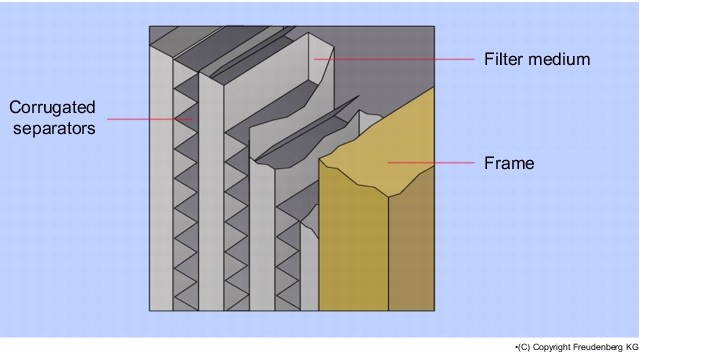
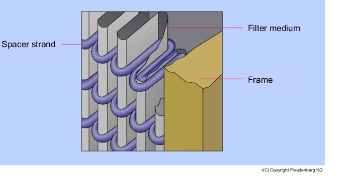
The filter media of suspended matter filters have a relatively high pressure differential. In order to accommodate as many filter surfaces as possible on the limited designed space, the filter medium is folded (see figure 3.H-22 and figure 3.H-23).
The older type of fold is the separator technique. The filter medium is folded lengthways and widthways alternately and a separator of corrugated aluminium is inserted in the resulting chambers, which prevents the filter medium from coming into contact with itself and thus creating an unusable filter surface. A disadvantage of the corrugated and sharp-edged aluminium separators is that they can tear the filter medium and create holes in it. This hazard applies during production, transport, fitting and in current operation through pulsing air currents.
The further development of the folding technique led to the strand design. The strand design technique allows the filter medium to fold with narrower spaces than the separator design. Thus, a greater filter surface can be realised in a suspended matter filter with a strand design of the same dimensions. The contact points of the spacers on the filter medium are significantly lower with the strand design than with the separator design
This technique results in the following advantages for suspended matter filters with a strand design:
- No mechanical stress on the filter medium through metal separators
- Lower height with the same dimensions and filter surface
- Lower pressure losses.
|
|
|
|
3.H.4 Principles for the design and planning
of air conditioning ventilation systems
When planning an air technology system, the principles must be clearly and unambiguously defined. For the ventilation systems to be designed and planned for a pharmaceutical manufacturing site, the external conditions of the site (see figure 3.H-24), the requirements of the premises (see figure 3.H-25), the production factors that influence the room climate (see figure 3.H-26) and the layout-dependent requirements (see figure 3.H-27) must be known.
Only if all conditions and requirements are known can an optimal ventilation system be designed and planned.
The data should be summarised in a room log which must be available to every person involved in the planning. (See chapter 3.B.6 Room book and layout.)
|
External conditions of the site |
|
|---|---|
|
External temperature |
|
|
Air humidity |
|
|
Sound limits |
|
|
Emissions of harmful |
|
|
Altitude |
|
|
Cardinal points |
|
|
Wind directions |
|
|
Requirements of premises |
|
|---|---|
|
Purity |
|
|
Pressure conditions |
|
|
Air flow direction |
|
|
Temperature |
|
|
Humidity |
|
|
Monitoring devices |
|
|
Noise |
|
|
Usage-dependent requirements |
|
|---|---|
|
Manufacturing type |
|
|
Hazard potentials of production materials or of the drug(s) |
|
|
Production times |
|
|
Reliability |
|
|
Recirculating air possible |
|
|
Special process air facilities for process equipment |
|
|
Sources of harmful |
|
|
EX - protection requirements |
|
|
Heat sources |
|
|
|
|
|
|
|
|
|
|
|
|
Staff clothing |
|
|
Layout-dependent requirements/dimensions |
|
|---|---|
|
Number of rooms |
|
|
Size of the rooms |
|
|
Height of the rooms |
|
|
Definitions for the facilities infrastructure |
|
|
Technology areas |
|
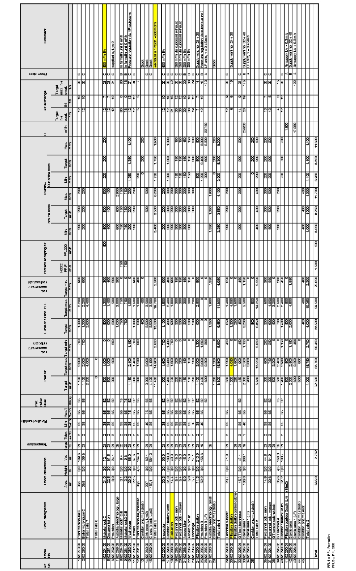
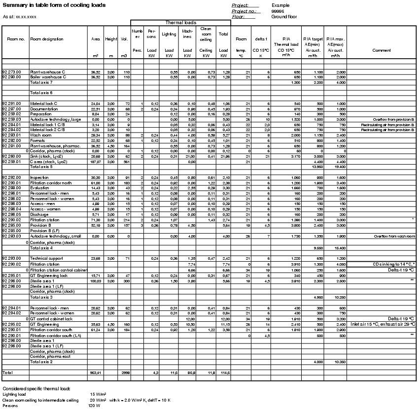
Evaluation of the principles
Using the formulated requirements and conditions, an air volume table can be compiled in relation to the rooms. The air volume table can be used to summarise all important data for the air technology system. Figure 3.H-31 to figure 3.H-35 and figure 3.H-28 contain two examples of a summary of the most important data, including
- General room data (room number, room name, area, height, volume etc.)
- Volume of inlet air, exhaust air, overflow air (min./max. values; per room)
- Air exchange (min./max. values; per room)
- Air volumes of special air technology systems
The second example shows the determination of the heat load in the room. This diagram is shown in Appendix 1 at the end of chapter 3 (Figure 3.H-31 to figure 3.H-35).
|
|
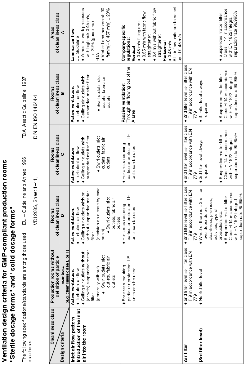
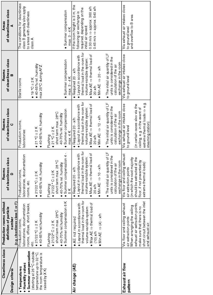
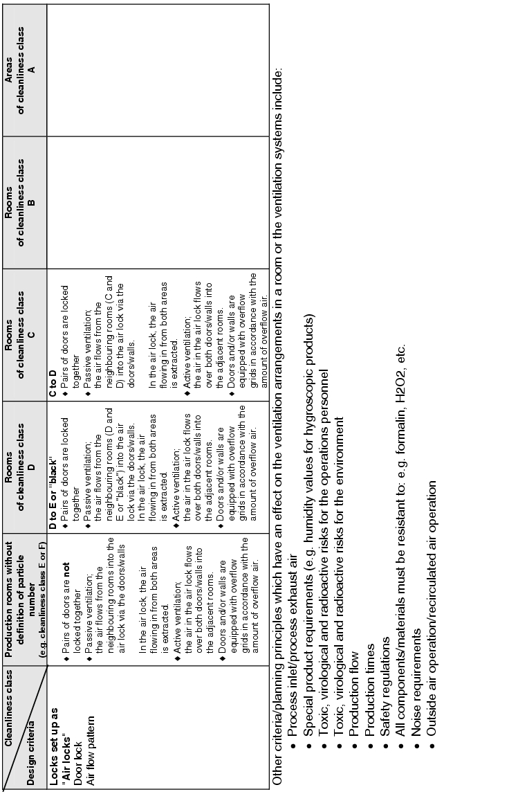
3.H.5 Design criteria for the ventilation of premises
The design of a room ventilation system for supplying the rooms is not specified accurately in the various GMP specifications and rules. The ventilation systems are to be designed so that adequate ventilation is achieved.
The actual implementation of the requirements for supplying the rooms with air means dealing with the following design criteria:
- How is the inlet air brought into the room? . ® Inlet air flow pattern
- How many filter stages are required and with what quality?
® Air filter/stages/air filter quality - Room conditions ® Temperature/humidity/summer compensation
- What air change is required? ® Air change
- How should the exhaust air be aspirated from the room? ® Exhaust air flow pattern
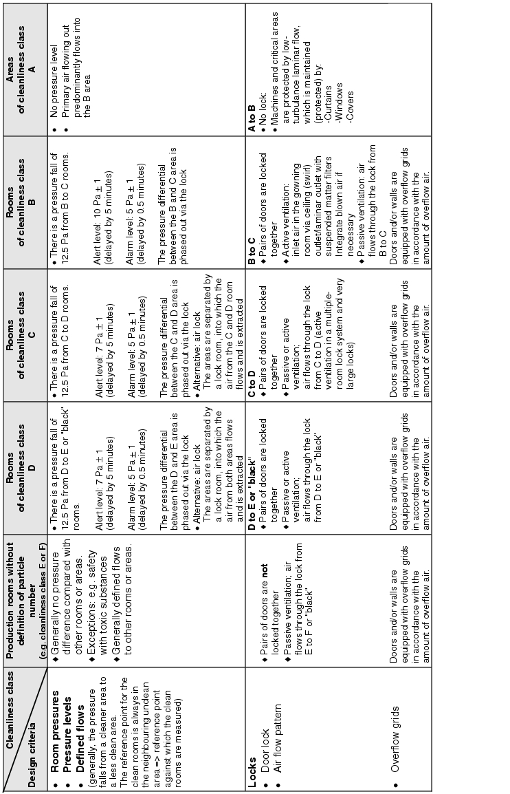
- Are pressure differences or defined flows required between rooms or areas?
® Room pressures/pressure stages/defined flows - How are locks designed? ® Door locking/air flow pattern
Figure 3.H-29 lists the basic design features with solution approaches for the design of the room supply. The data does not relate to the design of air technology equipment.
|
|
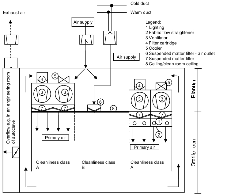
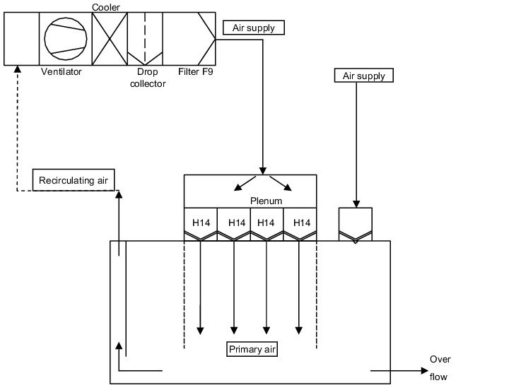
3.H.5.1 Air technology design of a sterile room with negative
pressure plenum
A sterile room with a negative pressure plenum has the following construction principles (see figure 3.H-29).
Above the sterile room, a second room is created which is connected to the sterile room via recirculating air ducts. The LF areas (filter fan units) are integrated in the ceiling between the sterile room and plenum. The filter fan units convey the air in the circuit between the sterile room and the plenum. The air is aspirated from the sterile room via aspiration points near the floor and conveyed to the plenum. In addition, the required fresh air is brought into the plenum as inlet air. The recirculating air and the inlet air are brought into the sterile room as initial air. Further inlet air can be brought in via area B through suspended matter filter air outlets. The excess air is allowed to flow into bordering areas, e.g. locks, engineering areas of autoclaves, etc. The overflow openings with constant air volumes are designed as gratings. Overflow openings can be fitted with adjustable flaps to control the pressure.
The diagram shows the main possibility of how a sterile room can be designed with a negative pressure plenum. Details about the technical solutions for all listed components can be found.
3.H.5.2 Pressure stages and design of the pressure differential
measurement for a sterile area
In accordance with the requirements, a pressure differential is realised between each cleanliness class. If each cleanliness area is measured at a reference point, this results in a clearly traceable record, e.g. with a line writer as the lines of the individual cleanliness areas are always offset by the pressure differential. As the individual traces must be offset and parallel, it is easy to recognise if the cleanliness areas have always been in the prescribed pressure area.
The diagram (see figure 3.H-30) shows how the individual pressure differentials are always measured in relation to a reference point. The alarms are determined from the differences between the cleanliness classes.
|
|
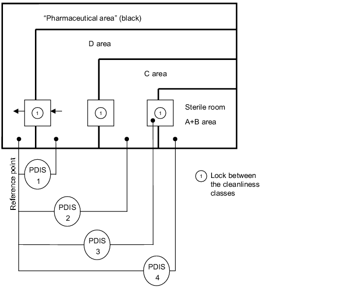
For example, the following values could result from the individual pressure differential measurements:
- PDIA 1: 12.5 Pa (pharmaceutical area/D area)
- PDIA 2: 25 Pa (pharmaceutical area/C area)
- PDIA 3: 32.5 Pa (pharmaceutical area/lock to sterile room)
- PDIA 4: 37.5 Pa (pharmaceutical area/sterile room)
Ventilation design criteria for GMP-conform production rooms
|
|
|
|
|
|
|
|
|
|
3.H.6 Maintenance of air ventilation systems
For pharmaceutical manufacturing sites, safe operation and functioning of the ventilation systems is an important requirement to be able to guarantee the manufacture of pharmaceutical products in accordance with specific requirements and conditions for the premises.
The required activities and concepts in relation to the operation of a ventilation system can be shown based on DIN 32541 (see figure 3.H-36).
|
|
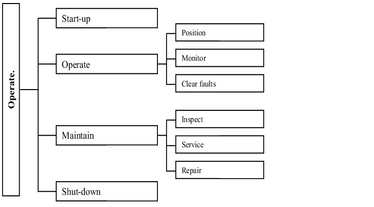
For operation, maintenance is an essential factor for preserving safe, fully functional and economic operation in terms of the required statuses (chapter 4.H Maintenance).
The following targets are pursued for air technology systems with planned and regularly executed maintenance measures (figure 3.H-37).
|
Maintenance |
||
|---|---|---|
|
Grouping of the measures |
||
|
Inspection |
Maintenance/Service |
Repair |
|
Targets of the measures = Definition in acc. with DIN 31051 |
||
|
Establishment and assessment of the actual status |
Preserving the required status |
Recovery of the required status |
|
Individual measures/activities |
||
|
|
|
- Guaranteeing and complying with physical parameters, such as temperature, humidity, pressure differences, etc.
- Guaranteeing a hygienic operation (purity, particle count etc.)
- Ensuring and increasing availability
- Guaranteeing economic operation (low energy costs)
- Identifying and eliminating weaknesses
- Maintaining the value of the system (longer life)
The "Building services engineering maintenance working group of the VDMA (association of German facility designer)" has issued data sheets which act as a standard for the execution of maintenance measures in the field of building services engineering. For all building services engineering areas, there are data sheets for maintenance (see figure 3.H-38).
|
VDMA data sheets |
Status/ Valid |
|
|---|---|---|
|
24 176 |
Inspection of air technology equipment and other technical equipment in buildings |
1/90 |
|
24 186 |
Performance programme for maintenance of air technology equipment and other technical equipment in buildings |
9/96 |
|
Part 0 |
Overview and structure, numbering system, general instructions |
9/96 |
|
Part 1 |
Air technology systems |
9/88 |
|
Part 2 |
Heating systems |
9/88 |
|
Part 3 |
Cooling systems |
9/88 |
|
Part 31 |
Electrically driven house heating pump systems for heating purposes |
4/86 |
|
Part 4 |
Measuring and control technology equipment and building automation systems |
9/88 |
|
Part 5 |
Electro-technical equipment and facilities |
4/96 |
|
Part 6 |
Sanitary systems |
5/92 |
|
24 196 |
Buildings management, terms and performances |
8/96 |
|
24 243 |
Emissions reduction of cooling agents from cooling systems |
|
|
Part 1 |
Introduction |
5/94 |
|
Part 2 |
Construction and planning |
5/94 |
|
Part 3 |
Assembly; Repair |
5/94 |
|
Part 4 |
Maintenance; Repair; Disposal |
5/94 |
|
Part 5 |
Specialist training, specialist plant equipment, operating instructions |
5/94 |
Inspection is the subject of the VDMA 24176 "Inspection of air technology equipment and other technical equipment in buildings" data sheet. Inspection includes testing and measuring activities, with the evaluation and assessment of the results being an essential task which should only be carried out by a specially trained employee. Exact knowledge of the actual status is an important requirement for planning maintenance measures.
Servicing includes the actual core task of planned maintenance. It includes all measures to ensure the required status of the ventilation system and is the subject of the VDMA 24186 "Performance programme for servicing of air technology equipment and other technical equipment in buildings" data sheet. Details of the various crafts of the technical building equipment are given in parts 0 to 6.
Based on the VDMA data sheets, it is possible to establish the measures to be executed for inspection and servicing and their documentation. From the extensive collection of activities in these data sheets, the corresponding performance pattern for the respective system can be compiled both for inspection and for servicing.
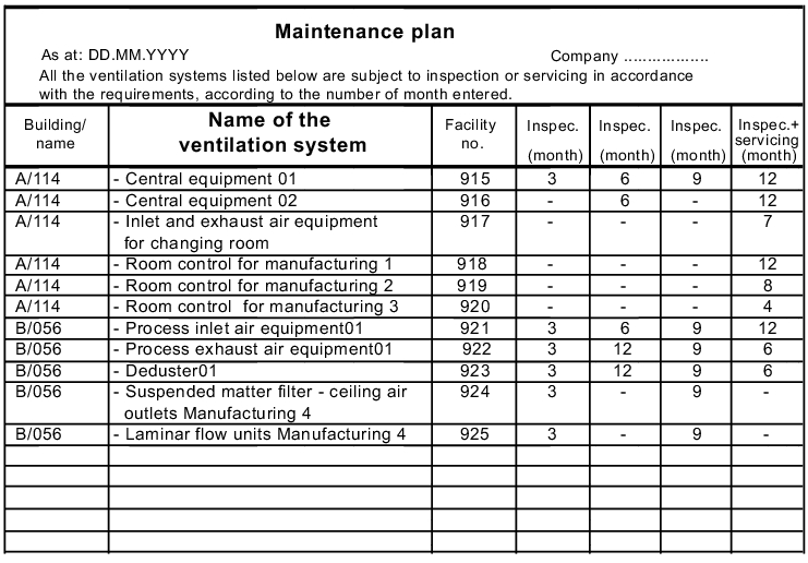
The deadlines and intervals for inspection and servicing are to be established in a maintenance plan (see figure 3.H-41). Based on experience, the manufacturer's specifications and the significance of the facility, periods must be defined in which an inspection or service is to be carried out (see figure 3.H-39). To this end, the permissible tolerance periods within which the inspection or servicing must be carried out should also be established (see figure 3.H-40).
Every maintenance measure must be documented. In general, for every activity on a ventilation system, an entry should be made in the log book to be stored on-site or in the operating diary of the respective system.
Documentation of the inspection or servicing activities that have been executed is carried out in the form of records which are filled in by the person executing the activity and counter-signed by a checker.
The following tables, records and diagrams show proven practical examples for the following maintenance activities for air technology systems:
- Time intervals for carrying out inspections or servicing (figure 3.H-39)
- Tolerances for inspection and servicing deadlines (figure 3.H-40)
- Maintenance plan (figure 3.H-41)
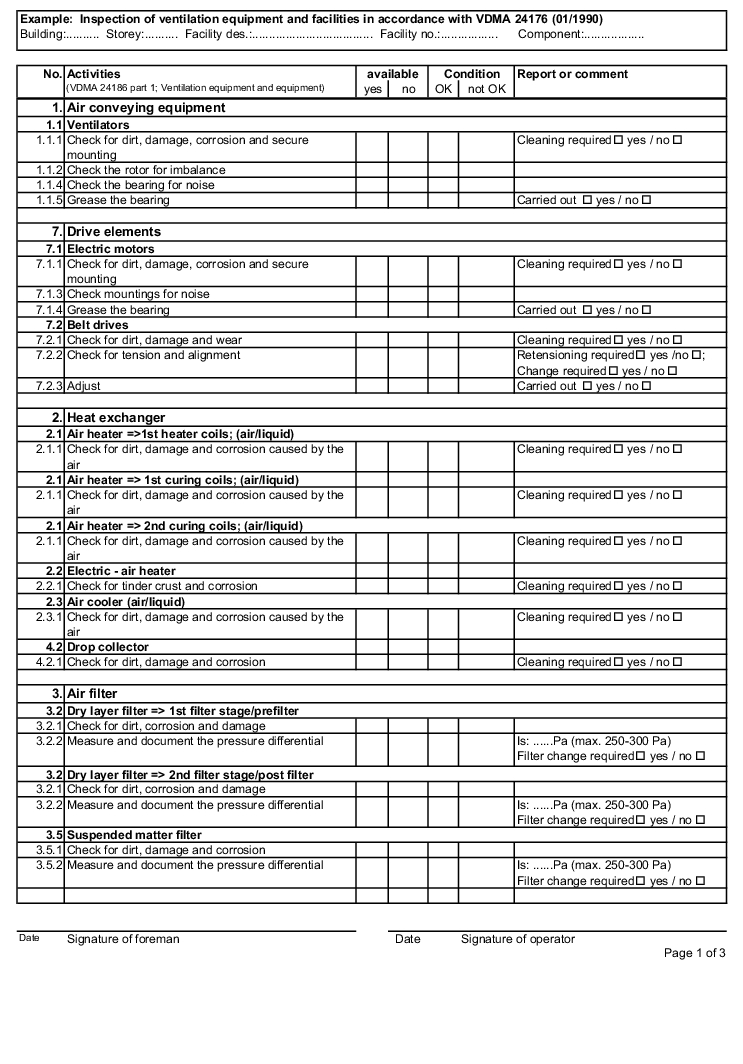
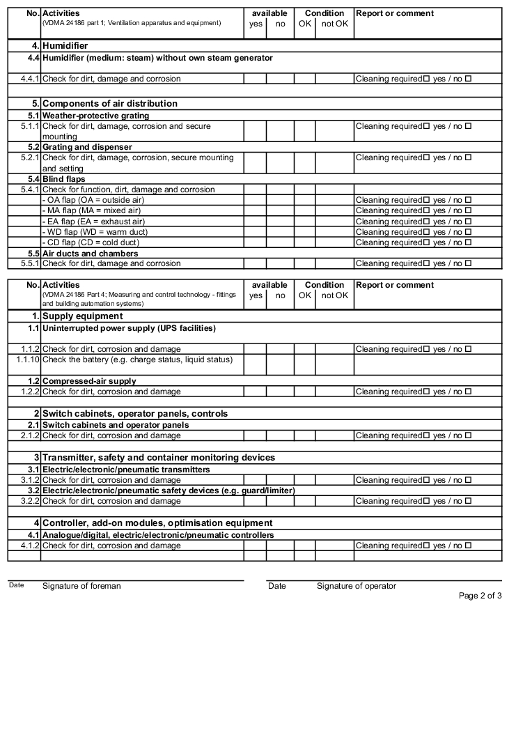
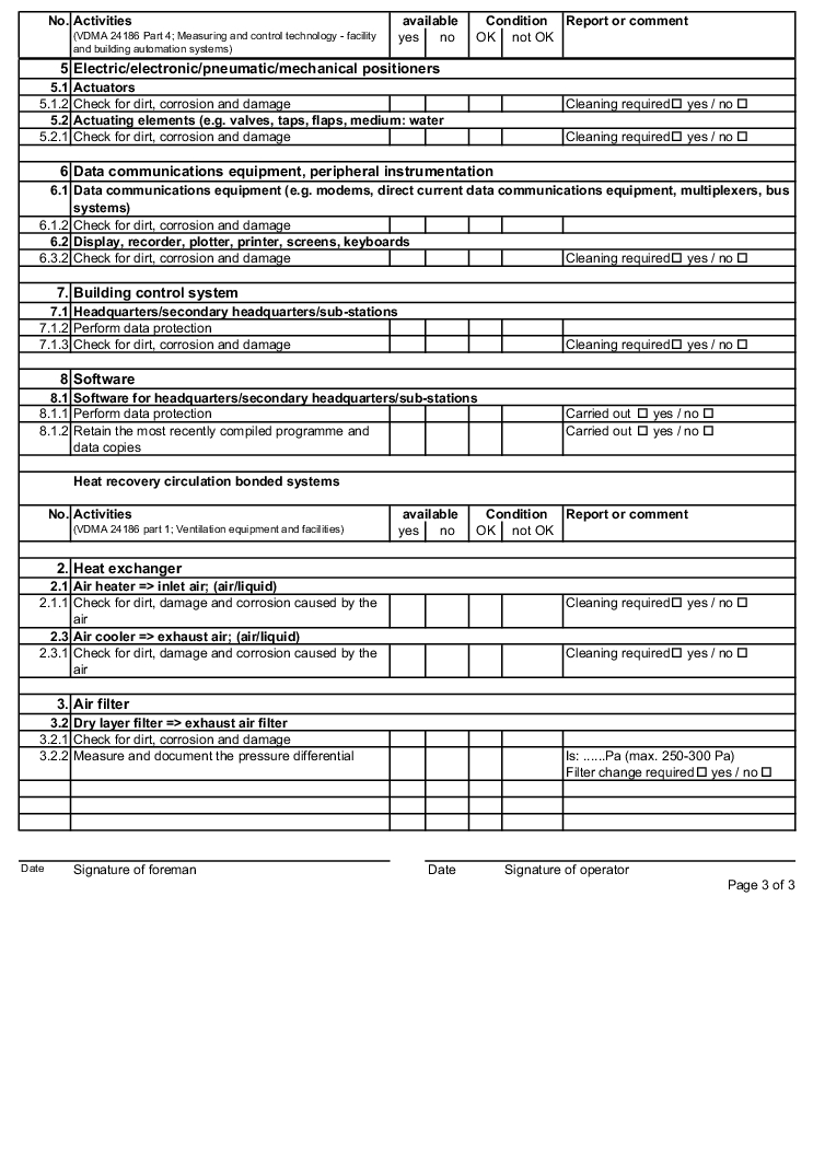
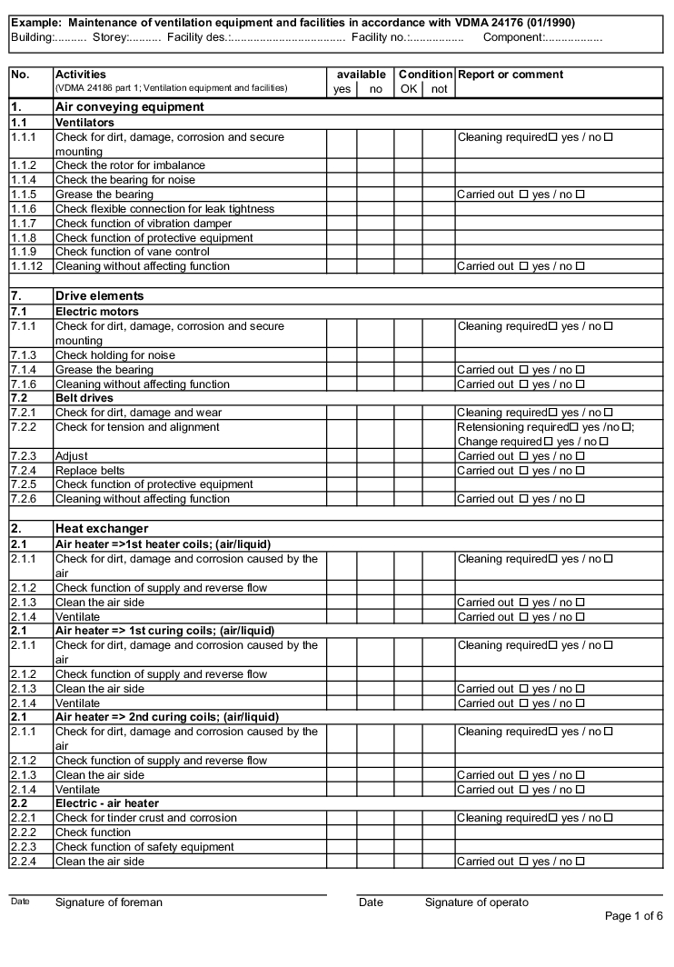
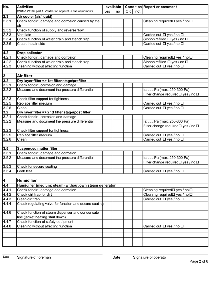
- Forms: Inspection of air technology equipment and systems (figure 3.H-42)
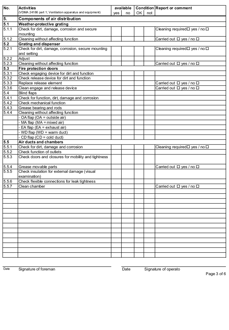
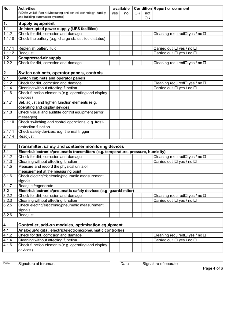
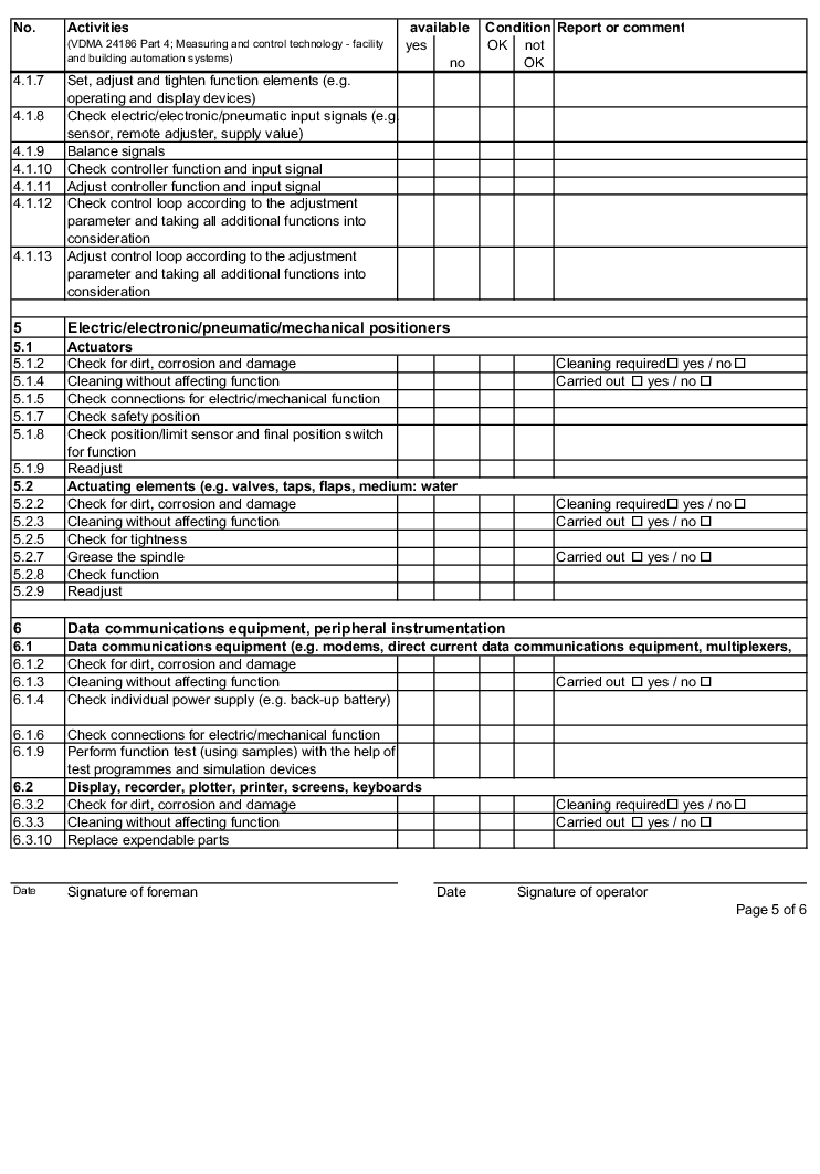
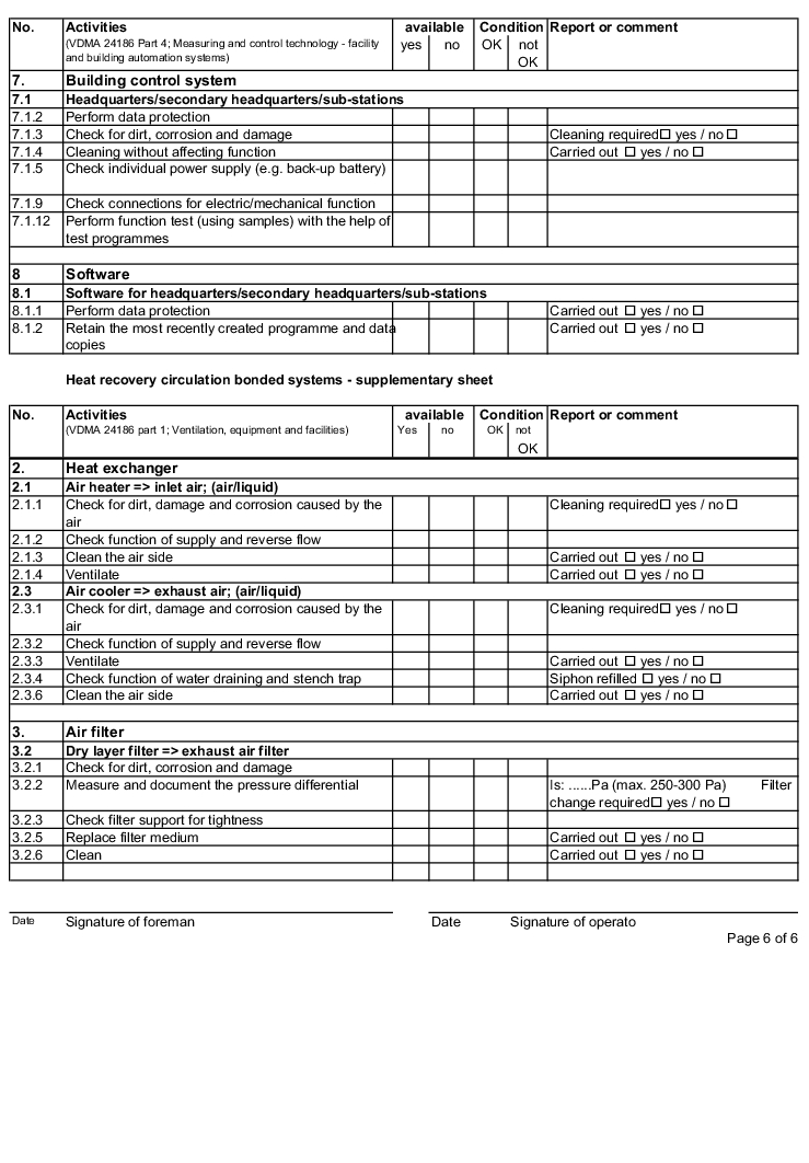
- Forms: Servicing of air technology equipment and systems (figure 3.H-43)
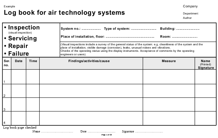
- Form: Log book for air technology systems (figure 3.H-45, figure 3.H-46, figure 3.H-47)
3.H.6.1 Time intervals for carrying out inspections or servicing
|
Frequency specifications relate to one year |
||||
|---|---|---|---|---|
|
Intervals |
No servicing |
1 x servicing |
1 x servicing and 1 x inspection |
1 x servicing |
|
Components |
||||
|
Ventilation equipment for: |
||||
|
x |
|||
|
x |
|||
|
x |
|||
|
x |
|||
|
Room control systems |
x |
|||
|
Process air systems |
x |
|||
|
Suspended matter filters |
x |
|||
|
Laminar flow units |
x |
|||
3.H.6.2 Tolerances for inspection and servicing deadlines
|
Deadlines for inspection and servicing |
Tolerance |
|---|---|
|
monthly |
± 2 weeks |
|
quarterly |
± 1 month |
|
half-yearly |
± 2 months |
|
yearly |
± 3 months |
3.H.6.3 Maintenance plan
|
|
3.H.6.4 Forms for the inspection and servicing of ventilation systems
The following examples of "Forms for the inspection and servicing of ventilation systems" are based on the VDMA data sheets. The activities listed are a selection from the "Performance programme for the servicing of air technology equipment and other technical equipment in buildings" from VDMA data sheets 24186 part 1 and 4.
The design and handling of forms is intended as follows. The following entries are to be made in the header of the forms:
- the building
- the storey
- the facility name
- the facility number
- the component (if required)
The following columns are to be filled in as shown, in the rows with the individually described activities: (The "available yes/no" column can be omitted if the forms only contain the components that are available on the air technology systems).
|
|
|
|
|
|
|
|
|
|
|
|
|
|
|
|
|
|
3.H.6.5 Log book for air technology systems
The log book can be bound or can consist of individual sheets. A bound version has proven better in practice, as this prevents the loss of individual sheets.
The example is structured as follows:
|
Column |
Entry |
|---|---|
|
"Available yes/no" |
Cross the corresponding box |
|
"Status" OK/not OK" |
Cross the corresponding box |
|
"Finding or comment" |
Here, findings, actual values, statuses that are not OK, executed activities, servicing activities, etc. are to be described in words. |
- A cover sheet (see figure 3.H-45))
- "Inspection, servicing, repair, malfunction" form" (page 1 to 20) (see figure 3.H-46)
- "Filter inspection, filter exchange" form (page 1 to 3) (see figure 3.H-47).
|
|
|
|
|
|

Principles for entries in the log book
(See chapter 15.B GMP-conforming documentation.)
- Entries in the log book are made on-site in chronological order (date and time) in the intended forms, by the person executing the activity
- The log book entry should be made during or immediately after completion of the activity. However, under no circumstances should it be signed before completion of the activity in question.
- After completion of the activity by the person executing the work, the entries are confirmed through the legible entry of a name and signature.
- After entry, any remaining blank fields are to be crossed out.
- The entries in a log book page must be checked for completeness and accuracy and initialled by a person in charge.
- Entries should only be made with permanent ink pens.
- The following entries must be made:
- Date/time of activity
- Type of activity, event (e.g. visual control, servicing, calibration, repair, malfunction)
- Signature or signatures
- An entry can be corrected by crossing it out. However, the old entry should still be legible after it has been crossed out. It is not permissible to cover the entry or delete it with Tipp-Ex. Correction or crossing out of an entry must then be confirmed by the person executing the task, with the date and signature.
3.H.7 Qualification of air conditioning
ventilation systems
Qualification of ventilation systems is incorporated in the overall concept of qualification for a manufacturing site. The overall qualification concept is described in a qualification master plan (see chapter 6.C.1 Qualification master plan). Thus, the qualification of ventilation systems is part of the overall qualification of manufacturing sites. The aim of the qualification of a ventilation system is to prove that the ventilation system is suitable for the manufacturing site in question.
The required scope of the qualification of ventilation systems depends on the extent to which compliance with the required parameters such as temperature, humidity, purity, pressure difference, etc. has a direct influence on the safe manufacturing of a pharmaceutical product. Therefore, it is first necessary to estimate which parameters are relevant for the products.
Example: For a heat-sensitive product, the "room temperature" parameter is clearly product-relevant, if, for example, the stability of the product is no longer given at a product temperature of 23 °C or higher, and the product is open when processed, without the possibility of direct cooling. Thus, for the room in which the heat-sensitive product is processed, it must be proven that the ventilation system can comply with the prescribed room temperature, e.g. 21 °C ± 1 K for all external conditions and that an alarm will be issued in the event of deviations.
On the other hand, there are many cases in which the room temperature does not have a direct influence on the product. It is therefore possible to define the room temperature purely in accordance with the comfort criteria for production personnel, in accordance with the recommendations of DIN 1946/Part 2. (Example: room temperature 22 °C ± 2 K and summer compensation, i.e. the room temperature is gradually increased to 26 °C as of an external temperature of 26 °C to 32 °C.)
The following checklists (figure 3.H-48) give an overview of the most important checks that must be taken into account during qualification of ventilation systems.
The following procedure has proven its worth in practice and has proven very viable:
- Definition of the necessary qualification scope for the air technology system between production managers and qualification managers
- The scope of qualification is documented in the checklists (figure 3.H-48 to figure 3.H-50) (fill in "Yes", "No" and Comments columns). In accordance with the area to be supplied (e.g. sterile/non-sterile/special product requirements), the qualification of the air technology system will include a greater or smaller number of points.
- Signing of checklists
- Compilation of detailed qualification plans based on the checklists
- Execution of the individual qualification steps in accordance with the individual phases (IQ, OQ and PQ)
- Compilation of the respective reports
If qualification of the ventilation system is to be carried out by external employees or with external support, the completed checklists can be used to request, offer and commission the scope of service to be provided externally by qualified providers.
|
Installation qualification (IQ) checklist |
required |
Comments |
|
|---|---|---|---|
|
yes |
no |
||
|
1.1 System description and specifications The aim is to document the requirements that must be met by the air technology system. If technical modifications that differ from the order are required by the manufacturer during production, these must also be documented. The following documents may be included in the system description or facility description: a) Drawings such as R&I flow charts, installation diagrams, isometries, etc. b) Requirements of the materials to be used c) Performance data for the system, including system components d) Definition of the type and quality of the utilities required for operation of the system, such as steam, water. |
|||
|
1.2 Documentation The documentation is to be available at the latest two weeks before the first acceptance deadline. The review of the documentation can extend over the entire period of the final acceptances and it is then to be revised in accordance with the correction notes. The form and scope of the documentation provided should be in accordance with the guidelines/requirements of ....in labelled DIN A4 folders. |
|||
|
The following documents can be included in the documentation:
|
|||
|
|||
|
|||
|
1.3 Installation checks The installation qualification includes several testing steps which are not only limited to final acceptance. The individual qualification checks are carried out throughout the entire construction phase. Final acceptance groups together the individual checks. |
|||
|
1.3.1 Quality check at the contract acceptor or its suppliers The contract giver reserves the right to check the following components of the contract acceptor's scope of delivery at the manufacturing site, at the construction site or in their final installation state. The check will be carried out in accordance with the following conditions. The following air technology equipment will be checked at the manufacturer:
|
|||
|
1.3.1.2 The control tests at the manufacturer, with improvement specifications, can concern the following points:
Deficiencies and deviations are documented in a deficiencies list |
|||
|
1.3.1.3 Pressure testing of ventilation components (e.g. air conditioning device). Air conditioning devices are subject to an endurance test. The pressure testing is carried out under the following conditions:
|
|||
|
1.3.1.4 Other required test criteria can be agreed and added to this checklist. 1 ... 2... 3 ... |
|||
|
1.3.2 Examination of the correct installation position of components The contract acceptor is obligated to compile a checklist for all components in his scope of delivery (e.g. fire protection flaps, volume flow regulators, blending boxes, flaps, air outlets, etc.), which permits easy and quick examination on-site (e.g. using order lists). The checklist should contain the test conditions and be compiled in the form of a table. The following are checked
|
|||
|
1.3.2.2 Duct tightness, permissible leak air flow for air conduction systems (DIN 24 194 Part 2) The permissible leak air flow is based on the tightness class of the air conduction system
with the assignment of the permissible leak air flow in
The test pressure corresponds to the intended system pressure from the outgoing connections of the ventilation equipment. The permissible leak air flows are to be taken from DIN 24 194 Part 2. Permissible leak air flow in (m3/s)/m2. During assembly of the air conduction system, a section of the installed duct system is tested. If this test has a negative result, the entire duct network will be subject to a duct tightness test. |
|||
|
Constructions, operating procedures, assembly instructions are to be compiled in accordance with the valid GMP Guidelines and agreed/approved with the contract giver. E.g.:
|
|||
|
1.3.3 Completeness test The completeness test on the system is carried out on-site, when installed, using approved assembly drawings and order lists supplemented with the test conditions. Testing is carried out on the basis of the VDI Directive 2079 "Final acceptance testing of ventilation systems". Test conditions: 1. Scope of delivery 2. Materials of components 3. Make of components 4. Correct installation of components 5. Safety devices available 6. Accessibility of components 7. Cleanliness status of the system 8. Inventory drawings 9. Operating instructions 10. Servicing instructions 11. Spare parts lists/spare parts 12. Test certificates/approval certificates (e.g. TЬV, Ex, fire protection flaps, pressure checks, etc.) |
|||
|
1.3.4 Calibration requirements A list is compiled with the measuring and control instruments to be calibrated, including the acceptance criteria. |
|||
|
1.3.5 Log book The form and scope in which a log book should be compiled is established for the system. |
|||
|
1.3.6 Operating procedures A decision is made on which operating procedures are required for the operation and servicing of the system. Existing operating procedures can be amended, used or new operating procedures can be compiled. 1............new/amend 2............new/amend 3............new/amend |
|||
|
1.3.7 Reports/servicing reports/malfunction reports A list is compiled with all reports, showing if the report concerns operation, servicing or a malfunction. |
|||
|
Operator/date_________________________________________________ |
|||
|
Quality assurance/date__________________________________________ |
|||
|
Production (user)/date__________________________________________ |
|||
|
Operational qualification (OQ) checklist |
required |
Comments |
|
|---|---|---|---|
|
yes |
no |
||
|
The operational qualification includes the review of the individual components for operability, based on VDI 2079. Specifically, the following are tests: |
|||
|
1. Ventilators |
|||
|
2. Filters |
|||
|
3. Heat exchangers |
|||
|
4. Humidification devices |
|||
|
5. Dehumidification devices |
|||
|
6. Heat recovery systems |
|||
|
7. Post-treatment equipment |
|||
|
8. Air ducts |
|||
|
9. Fire protection flaps |
|||
|
10. Air flaps |
|||
|
11. Filter seals |
|||
|
12. Volume flow regulators |
|||
|
13. Blending boxes, expansion boxes |
|||
|
14. Air openings |
|||
|
15. Measuring and control equipment |
|||
|
16. Calibrations of all sensors |
|||
|
17. Test of the reports/alarm functions |
|||
|
18. Heat supply |
|||
|
19. Cold supply |
|||
|
20. Power supply |
|||
|
21. Steam supply |
|||
|
22. Condensate/water draining |
|||
|
A list is created for each of the above-mentioned components, in which the tests to be carried out are established along with the acceptance criteria to be complied with. |
|||
|
Operator/date_________________________________________________ |
|||
|
Quality assurance/date__________________________________________ |
|||
|
Production (user)/date__________________________________________ |
|||
|
Performance qualification (PQ) checklist |
required |
Comments |
|
|---|---|---|---|
|
yes |
no |
||
|
Performance qualification means testing all given performance features, such as volume flow, pressure, humidity, temperature, air exchange counts, overflow devices, pressure differential values, air velocities, etc. The performance qualification also includes testing of the individual measuring methods, execution of the measurements, the type of documentation, in particular the description and calibration of the measuring instruments. |
|||
|
In addition to this, the test also includes the special requirements for testing clean rooms and their components, which are required to achieve the required particle count or classification. Performance qualification is to be carried out by the contract acceptor and must be assigned the following contents. |
|||
|
3.1 Describe the aims of the PQ |
|||
|
3.2 Description of all measuring instruments used (e.g. measuring principle, measuring range, tolerances, etc.) |
|||
|
3.3 Testing of areas with and without defined particle count and ranges In general, a PQ is carried out for each piece of equipment, each facility and each room. In each case, the required values and actual values for the respective test requirements are to be listed in the form of tables with clear assignment. 3.3.1 Testing of areas without a defined particle count The PQ is carried out on the basis of VDI 2079 and includes the following verifications: 3.3.1.1 Equipment testing 1. Power consumption and performance determinations of the drive motor 2. Pressure drop per item of equipment 3. Air supply temperature 4. Inlet air humidity 5. Response limit of safety equipment 6. Safety switches 7. Register performance: 8. Noise level in air current and outside the equipment 9. Efficiency of the heat recovery, proof of performance for heat recovery |
|||
|
10. Blending rate for recirculating air mixing, blending ratio and heat distribution after recirculating air mixing (operational proof of blenders). 11. Volume flow 12. Filter pressure difference |
|||
|
3.3.1.2 System testing 1. Air temperature in the storey distribution channel or at the end of the main distribution channel 2. Air humidity in the storey distribution channel or at the end of the main distribution channel 3. Air currents and velocities in the main channels and storey connections 4. Pressure drop in the main channels and storey distribution channels 5. Response limits of safety devices and safety sequenced actuation 6. Register performance, register pressure losses on air and water side for central post-treatment zones |
|||
|
3.3.1.3 Room testing 1. Air supply temperature at air outlet 2. Exhaust air temperature at room exit 3. Inlet and exhaust air volume flow with calculated 4. Room temperature 5. Room air velocity 6. Room air humidity 7. Noise level 8. Overflow equipment in all openings 9. Room positive pressure to bordering rooms (D P) 10. Calculated proof of minimum external air rates |
|||
|
3.3.2 Additional tests for areas with a defined particle count |
|||
|
3.3.2.1 Testing the air exchange of clean areas (class B, C, D)
|
|||
|
3.3.2.2 Testing the air velocity with low-turbulence laminar flow in accordance with operating procedure XXX If there is no operating procedure, the execution of the measurement must be described in detail. |
|||
|
3.3.2.3 Proof of pressure zones
|
|||
|
3.3.2.4 Testing suspended matter filters
With duct suspended matter filters and suspended matter filters on the aspiration side, e.g. for process exhaust air, a suitable construction must be selected to enable these tests (e.g. install a special test ventilator) |
|||
|
3.3.2.5 Proof of the cleanliness classes in accordance with DIN EN ISO 14644-1
|
|||
|
3.3.2.6 Flow pattern for class A/B and C
The proof is to be documented visually with a video film, photos and an extensive report. |
|||
|
3.3.2.7 Recovery time Testing of the recovery time of the clean room (e.g. class A/B) for:
|
|||
|
Operator/date_________________________________________________ |
|||
|
Quality assurance/date__________________________________________ |
|||
|
Production (user)/date__________________________________________ |
|||
|
Summary The term "air technology" is split into the two terms "ventilation technology" and "process air technology". The ventilation system used is essentially determined by the following factors:
In principle, it must be clarified if a recirculating air system is possible. In order to guarantee the purity of the air in the premises of a pharmaceutical manufacturing site, suitable filters must be used. The design of a suitable ventilation system requires detailed recording of the planning principles and specification of the GMP requirements in implementable designs. The safe, fully functional and economic operation of a ventilation system requires a maintenance system. A prerequisite for the use of a ventilation system in a pharmaceutical manufacturing site is that the systems can be qualified. |
